
Flat material loading device

A flat plate and support plate technology, applied in the field of machinery, can solve the problems of small up and down moving distance of the suction cup arm, high material cost and operating cost, long suction cup arm, etc., so as to increase the moving distance, low material cost and operating cost, The effect of reducing the length

Inactive Publication Date: 2014-11-05
GLASTONTIANJINCO
View PDF14 Cites 0 Cited by
  • Summary
  • Abstract
  • Description
  • Claims
  • Application Information

AI Technical Summary

Problems solved by technology

[0005] But the suction cup arm of above-mentioned loading device is long and heavy, and material cost and running cost are all higher; For glass or coated glass, it is a very serious problem; at the same time, because the distance that the suction cup arm can move up and down relative to the flip arm is very small, it can only be used for slicing. When it reaches the reference side, it will be greatly restricted, which will affect the cooperation between processes

Method used


Image

  • Flat material loading device
  • Flat material loading device
  • Flat material loading device

Examples


no. 3 example

[0046] The structure of the frame, the rotating arm support frame and the like of the third embodiment of the present invention are the same as those of the first embodiment, except that a suction cup is fixedly arranged above the outside of the suction cup base, and a There is a support plate made of spring plate or steel plate whose upper end is hinged with the suction cup base, the support plate can swing relative to the suction cup base, wherein two suction cups are fixedly connected with the support plate.

[0047] In this embodiment, when the flat material loading device of this embodiment is in operation, when the suction cup is in contact with the flat material and sucks the vacuum, because the suction cup fixed on the support plate is sucking the flat material, the deformation caused by the suction cup will simultaneously pull the support plate toward At this time, the suction cup fixed on the top of the suction cup base has sucked the flat material and achieved V-shap...


PUM


Abstract

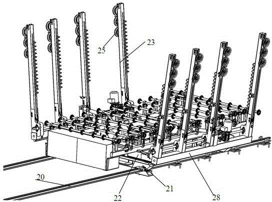
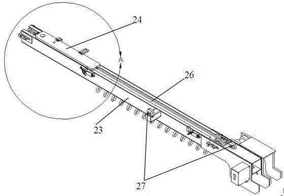
A flat material loading device, comprising a rack (21), a turning arm support frame (22) moving horizontally along the rack (21) and a plurality of turning arms (23) with one end fixedly connected to a turning arm base (28). The turning arm base (28) can be rotatably connected to the turning arm support frame (22). Sucker bases (24) capable of moving up and down under driving along the extending directions of the turning arms are arranged on the turning arms (23), and at least one sucker (25) is arranged on the sucker base (24). In the device, the sucker bases (24) are used for replacing sucker arms, which reduces the length and mass; simultaneously, positions of the suckers (25) are concentrated, therefore when the flat materials are sucked and separated, actions happened to the flat materials are swing with the lower portions still, namely, a V-type separation, scrapes to the following flat materials are avoided; simultaneously, the sucker bases can move up and down on the turning arms, so that the flat material suction specification is the same on the datum side and the non-datum side, and the sucking range during suction of the flat materials on the non-datum side is increased.

Description

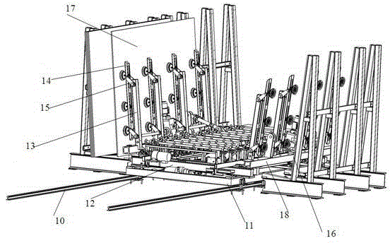
technical field [0001] The invention relates to the technical field of machinery, in particular to a flat material loading device. Background technique [0002] In the production and preparation of flat materials, such as glass, slate, etc., due to the need for a large amount of handling of flat materials, the industry usually uses suction cups to first suck the flat materials, and then move the flat materials to the required position. The device is often referred to as a loader or a flat material loader. [0003] figure 1 Shown is a schematic structural view of a flat material loading device in the prior art. Such as figure 1 As shown, the chip loading machine includes a frame 11 installed on the ground or on the guide rail 10, a flip arm support frame 12 that is installed on the frame and can move left and right relative to the frame and is provided with transmission rollers, is arranged on the flip arm support A plurality of turning arms 13 on both sides of the frame,...

Claims


Application Information

Patent Timeline
Patent Type & Authority Patents(China)
IPC IPC(8): B65H3/08
CPCB65G49/068B65G2249/04
Inventor 覃华德
Owner GLASTONTIANJINCO
Learn More