
Device for liquefying and purifying natural gas

A technology of natural gas and gas-liquid separator, which is applied in the field of natural gas purification and liquefaction, can solve the problems of large area, large investment, large equipment investment, etc., and achieves small area, low investment, and large promotion and application value. Effect

Inactive Publication Date: 2013-01-09
SHENZHEN LK SCI&TECH
View PDF4 Cites 4 Cited by
  • Summary
  • Abstract
  • Description
  • Claims
  • Application Information

AI Technical Summary

Problems solved by technology

[0002] At present, in terms of natural gas liquefaction: the process is complicated, and purification is required before liquefaction (the purification process is very complicated), and the investment in equipment is large
[0003] In terms of natural gas purification: the purification mainly includes dehydration, removal of light hydrocarbons (hydrocarbons above C3+), deacidification, and mercury removal. Currently, the main methods include molecular sieve method and absorption adsorption method. large area

Method used


Image

  • Device for liquefying and purifying natural gas
  • Device for liquefying and purifying natural gas
  • Device for liquefying and purifying natural gas

Examples


Embodiment 1

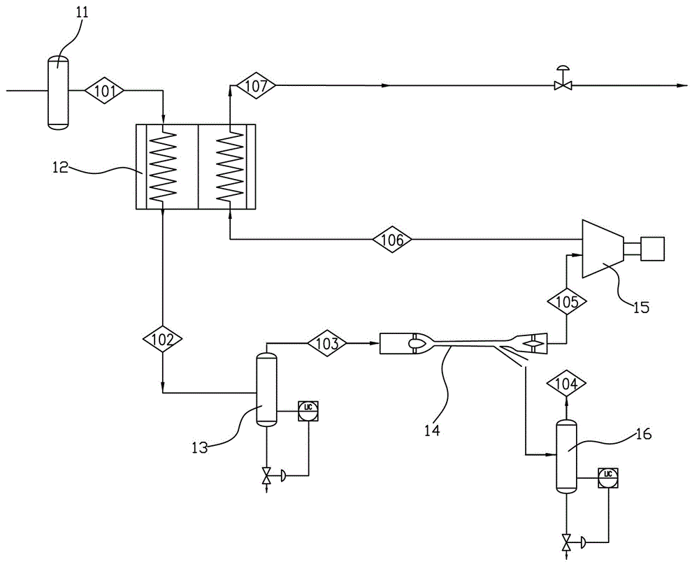
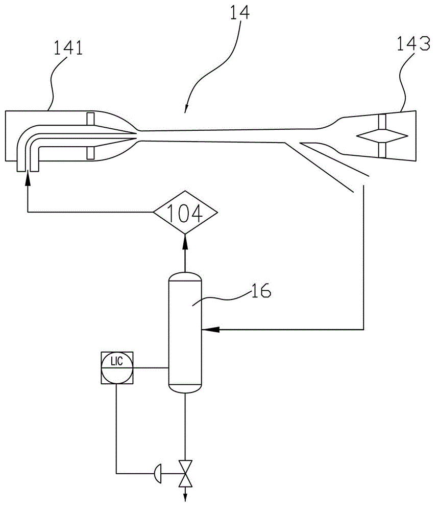
[0024] Such as figure 1 , 2 As shown, the device for liquefying and purifying natural gas provided by Embodiment 1 of the present invention includes a dehydrator 11, a heat exchanger 12, a first gas-liquid separator 13, a supersonic condenser 14, and an expansion refrigeration device 15 connected in sequence. The output end of equipment 15 communicates with the input end of heat exchanger 12;

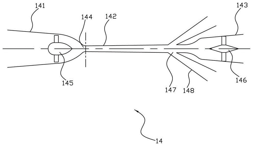
[0025] Wherein, the supersonic condenser 14 includes a constriction tube 141, a supersonic condenser tube 142 and a diffuser tube 143 which are connected coaxially in sequence from left to right. Throat 144, the supersonic condenser tube 142 extends from the narrow throat 144 from left to right and the cross-section gradually becomes larger, the cross-section of the diffuser pipe 143 gradually becomes larger from left to right, and a rotating mechanism 145 is arranged in the shrinkage pipe 141, and the diffuser A deflector 146 is provided in the pipe 143 , and at least one separation ...

Embodiment 2

[0035] Such as Figure 4 , 5 As shown, the device for liquefying and purifying natural gas provided by Embodiment 2 of the present invention includes a heat exchanger 22, a first gas-liquid separator 23, a supersonic condenser 24 and an expansion refrigeration device 25 connected in sequence, and the output of the expansion refrigeration device 25 is The end communicates with the input end of the heat exchanger 22.

[0036]Wherein, the supersonic condenser 24 includes a constriction tube 241, a supersonic condensing tube 242 and a diffuser tube 243 which are connected coaxially in sequence from left to right. Throat 244, supersonic condensing pipe 242 extends from left to right from narrow throat 244 and the cross section becomes larger gradually, and the cross section of diffuser pipe 243 gradually becomes larger from left to right. A deflector 246 is provided in the pipe 243 , and at least one separation outlet 247 is opened on the supersonic condenser pipe 242 , the separ...

Embodiment 3

[0043] Such as Figure 7 , 8 As shown, the device for liquefying and purifying natural gas provided by Embodiment 3 of the present invention includes a heat exchanger 32 , a first gas-liquid separator 33 and a supersonic condenser 34 connected in sequence.

[0044] Wherein, the supersonic condenser 34 includes a constriction tube 341, a supersonic condenser tube 342 and a diffuser tube 343 which are connected coaxially in sequence from left to right. Throat 344, supersonic condenser tube 342 extends from left to right from narrow throat 344 and the cross section becomes larger gradually, and the cross section of diffuser pipe 343 gradually becomes larger from left to right, and a rotating mechanism 345 is arranged in shrinkage pipe 341, and the diffuser A deflector 346 is provided in the pipe 343, and at least one separation outlet 347 is provided on the supersonic condenser pipe 342, and the separation outlet 347 is connected with a separation pipe 348, and the separation pi...


PUM


Abstract

The invention relates to a device for liquefying and purifying natural gas. The device comprises a dehydrater, a heat exchanger, a first gas-liquid separator, an supersonic speed condenser and expansion refrigeration equipment which are communicated sequentially, wherein the output end of the expansion refrigeration equipment is communicated with the input end of the heat exchanger; the supersonic speed condenser comprises a shrinkage pipe, a supersonic speed condenser pipe and a diffuser pipe which are communicated sequentially and coaxially from left to right; the cross section of the shrinkage pipe is reduced gradually from left to right and is shrunk from the middle to form a narrow throat; the supersonic speed condenser pipe extends from left to right from the narrow throat, and the cross section of the supersonic speed condenser pipe is increased gradually; the cross section of the diffuser pipe is increased gradually from left to right; a rotary mechanism is arranged in the shrinkage pipe; a flow deflector is arranged in the diffuser pipe; at least one separation outlet is formed in the supersonic speed condenser pipe and is connected with a separation pipe; and the separation pipe is connected with a second gas-liquid separator. According to the device, the supersonic speed condenser is used as core equipment to liquefy and purify the natural gas, so that a process for liquefying and purifying the natural gas is simplified; and the device is small in floor space and low in investment.

Description

technical field [0001] The invention belongs to the technical field of low-temperature refrigeration, and in particular relates to a device for liquefying and purifying natural gas. Background technique [0002] At present, in terms of natural gas liquefaction: the process is complicated, purification must be carried out before liquefaction (the purification process is very complicated), and the investment in equipment is large. [0003] In terms of natural gas purification: the purification mainly includes dehydration, removal of light hydrocarbons (hydrocarbons above C3+), deacidification, and mercury removal. Currently, the main methods include molecular sieve method and absorption adsorption method. The grounds are large. Contents of the invention [0004] The object of the present invention is to overcome the shortcomings of the above-mentioned prior art and provide a device for liquefying and purifying natural gas with simple flow, small footprint and low investment...

Claims


Application Information

Patent Timeline
IPC IPC(8): C10L3/10
Inventor 邢小月杜岳
Owner SHENZHEN LK SCI&TECH
Learn More