Electric vacuum pumps for motor vehicles

A vacuum pump and fresh air technology, applied in the direction of machines/engines, rotary piston/oscillating piston pump components, pumps, etc., can solve the problems of high labor cost, large material cost, long cycle, etc., to reduce use and shorten time, to avoid the effect of vacuum pump overheating

Active Publication Date: 2016-01-20
FORD GLOBAL TECH LLC
View PDF7 Cites 0 Cited by
  • Summary
  • Abstract
  • Description
  • Claims
  • Application Information

AI Technical Summary

Problems solved by technology

This not only creates long cycle times in the workshop, but also creates considerable costs, not only high labor costs, but also, in particular, considerable material costs for the entire vacuum pump

Method used


Image

  • Electric vacuum pumps for motor vehicles
  • Electric vacuum pumps for motor vehicles
  • Electric vacuum pumps for motor vehicles

Examples


Embodiment Construction

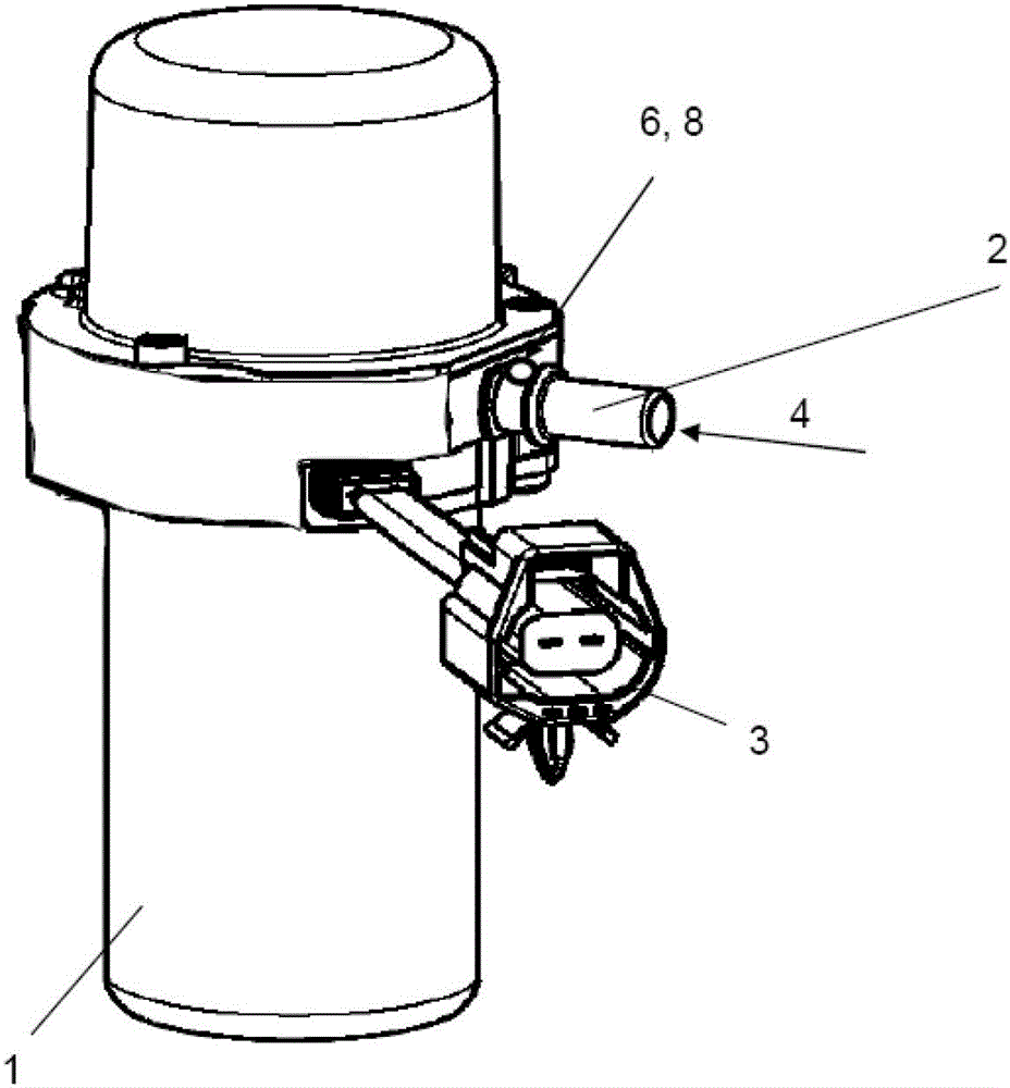
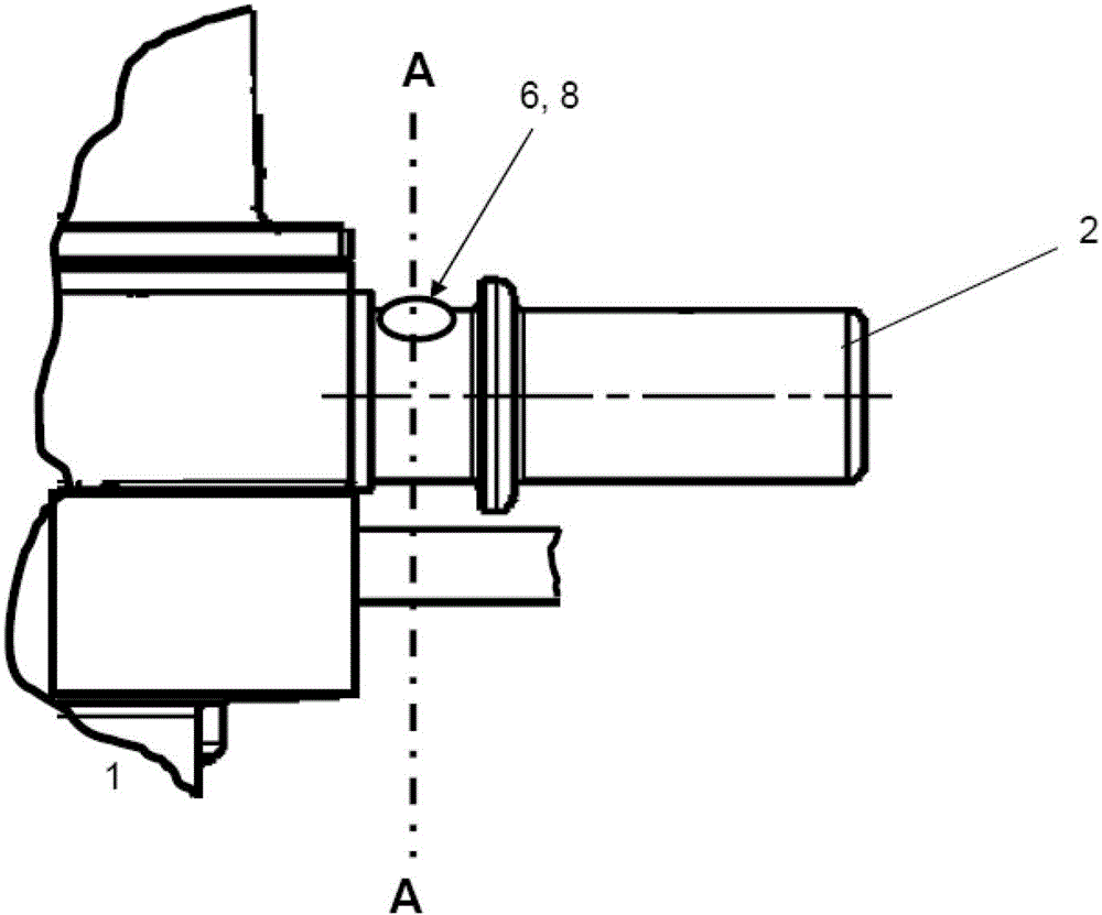
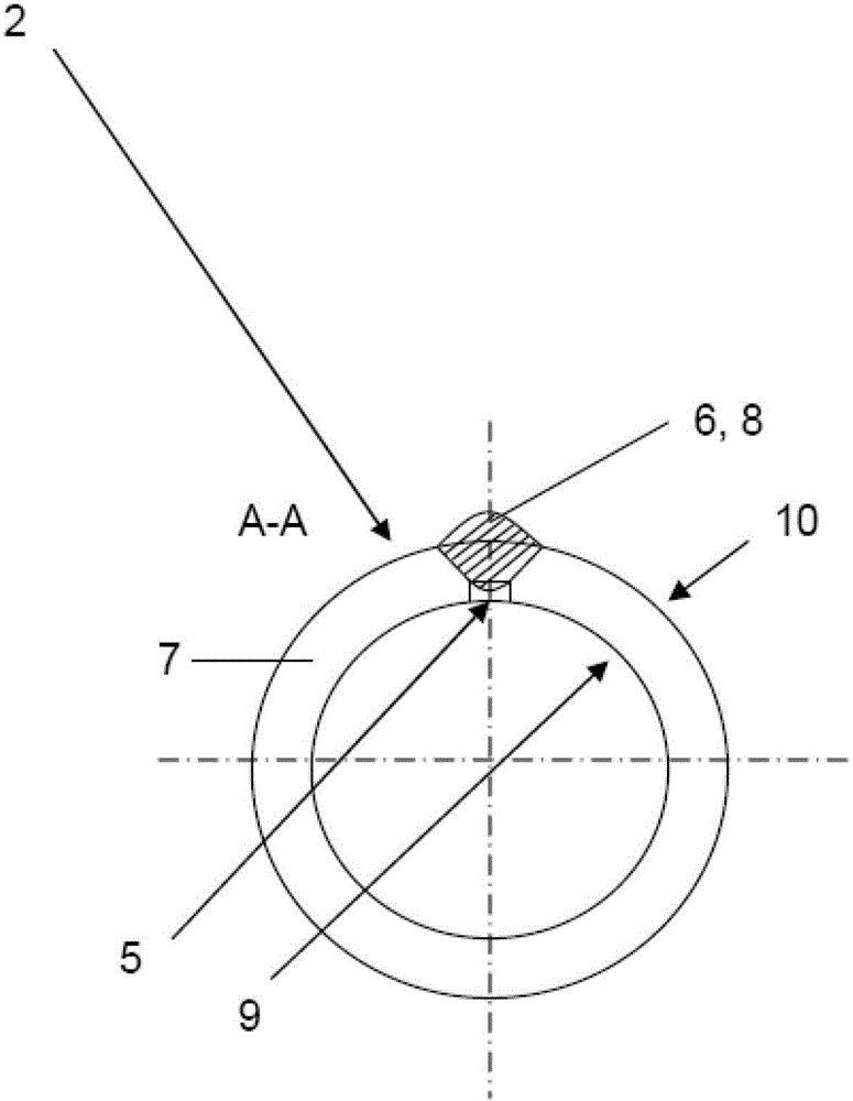
[0024] figure 1 Represents a vacuum pump 1, specifically, a vane vacuum pump 1 whose inlet connector 2 is connected to a unit (not shown) that will generate negative pressure through a connecting pipeline (not shown in the figure), the vacuum pump 1 A check valve (not shown in the figure) is provided between the vacuum pump 1 and the unit, and the vacuum pump 1 is controlled by a monitoring unit (not shown in the figure).

[0025] In the present example, the vacuum pump 1 is driven electrically, for which purpose a corresponding electrical connector 3 is provided. The monitoring unit can be connected with the electrical connector. The monitoring unit causes the vacuum pump 1 to switch on and off and thus enter into an operating state.

[0026] For example, when the vacuum pump 1 is in operation, the unit that will generate negative pressure is the brake servo unit.

[0027] When the vacuum pump 1 has been in operation, it sucks the medium from the unit into the suction cham...


PUM


Abstract

The electrically driven vacuum pump (1) is connected with an aggregate at an inlet port (2) through a connecting line. A negative pressure is generated in the aggregate, where a check valve is arranged between the vacuum pump and the aggregate. A control and monitoring unit is arranged, where an opening is formed downstream of the check valve. The opening is enclosed by a refractory material (6) which melts at a predetermined melting temperature. The refractory material is made of a plastic material, particularly synthetic resin.

Description

technical field [0001] The present invention relates to a kind of vacuum pump, relate to a kind of vane cell vacuum pump in particular, its inlet connector is connected with the unit through connecting pipeline, will produce negative pressure in the unit, there is check valve between vacuum pump and unit, vacuum pump can be monitored by unit control. Background technique [0002] Both patent documents DE102004012736A1 and DE2356398 disclose fusible security devices, neither of which is relevant to the class of this patent. [0003] Vacuum pumps, in particular vane vacuum pumps, are known in automotive technology, which are able to generate a vacuum in the brake servo (unit). Therefore, the basic structure of the vane vacuum pump will not be discussed in detail. [0004] It is known that these vacuum pumps can be driven electrically, their operation being controlled by a monitoring unit. Thus, the vacuum pump can be turned on and off according to the signal generated by th...

Claims


Application Information

Patent Timeline
Patent Type & Authority Patents(China)
IPC IPC(8): F04C28/28F04C29/04
CPCF04C29/04F04C18/344F04C25/02F04C28/28
Inventor 马丁·塔尔诺夫
Owner FORD GLOBAL TECH LLC
Why Eureka
Try Eureka