A plywood pressing equipment
A technology for plywood and equipment, applied in the field of plywood pressing equipment, can solve problems such as burns, and achieve the effects of reducing travel, reducing labor intensity, and reducing the risk of burns
- Summary
- Abstract
- Description
- Claims
- Application Information
AI Technical Summary
Problems solved by technology
Method used
Image
Examples
Embodiment 1
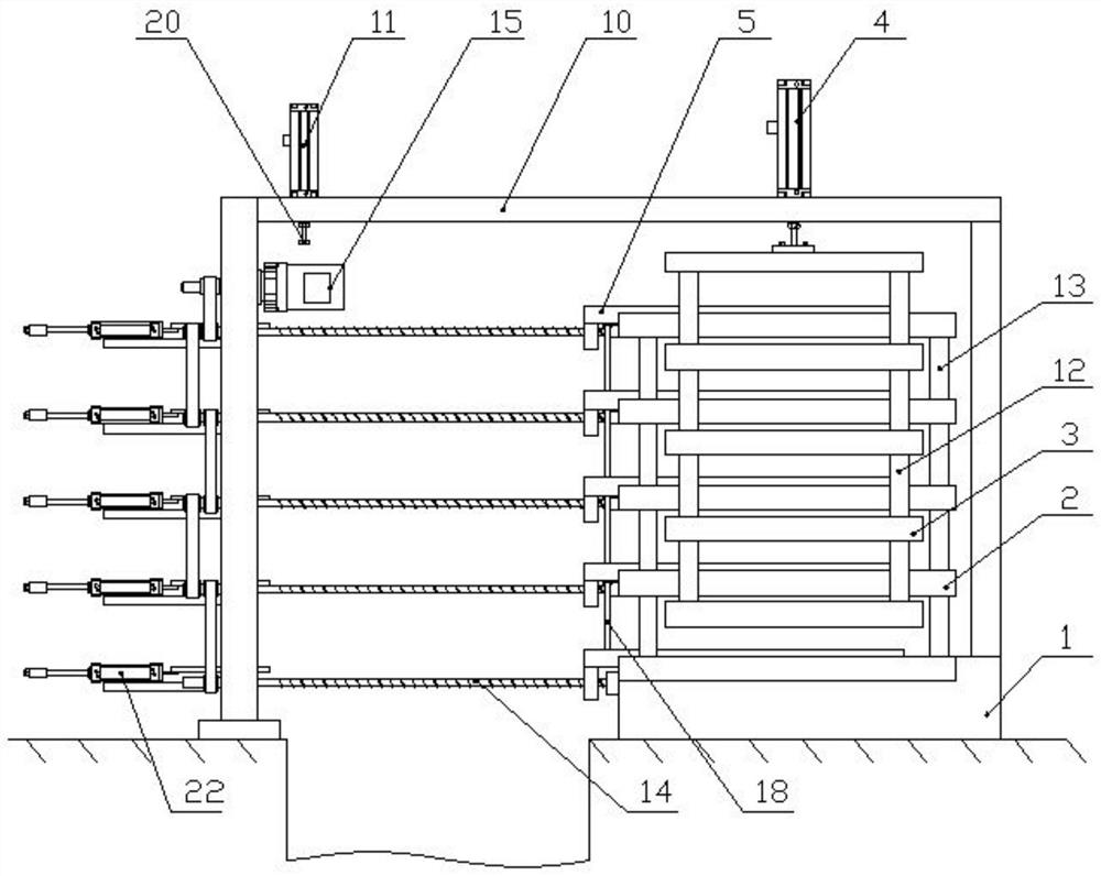
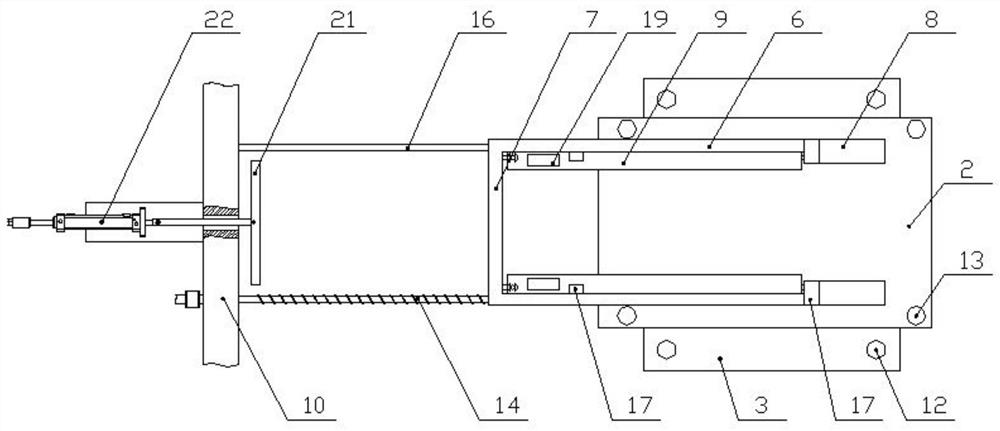
[0022] Example 1: Such as Figure 1 - Figure 3 As shown, the specific structure of the present embodiment is: it includes a base 1, and the upper end of the base 1 is provided, and the upper end of the base 1 is provided with a pair of upper hot plate 3 and the lower heat pressure plate 2, upper heat The pressure plate 3 is located above the lower heat pressure plate 2, the upper hot press plate 3 to the recovery drop in the action of the hot press drive 4, the hot press drive 4 can be used in linear actuators such as cylinders, hydraulic cylinders, electric push rods. The lower end face interval interval is provided with a slide, the chute side, and when hot press, the slab is placed in the slab placing frame 5, the slab placing frame 5 includes a horizontal interval. The arranged beam 6 and the connecting plate 7 disposed between the two beams 6, the beam 6 inserted from the lower heat pressure plate 2 side end from the lower heat pressure plate 2 on the side end of the slot 8, a...
Embodiment 2
[0024] Example 2: Such as Figure 1 - Figure 2 As shown, other structures in this embodiment are the same as in Example 1, but in the present embodiment, a multi-block slab is machined, and the upper hot press plate 3 and the lower heat pressure plate 2 are arranged in a vertical direction, and The upper heat pressure plate 3 and the lower heat pressure plate 2 are arranged in a mutually interlaced manner, and the upper thermal pressure plate 2 is formed with a hot pressing unit, and the upper hot plate 3 has a long side and a lower hot press. The width side of the plate 2 is on the same side, so that the upper hot press plate 3 and the lower heat pressure plate 2 extends from the other side, and the support column 12 is disposed between the two upper hot press plates 3, adjacent two A vertical column 13 is disposed between the lower heat pressure plate 2, and the lowermost thermal pressure plate 2 is disposed on the upper end of the base 1, and the uppermost heat pressure plate 3 ...
Embodiment 3
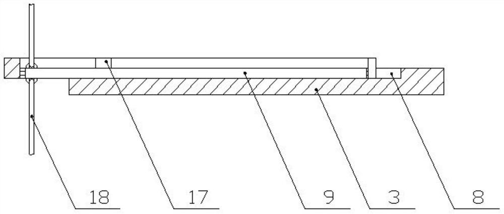
[0025] Example 3: Such as Figure 2 - Figure 3 As shown in the present embodiment, the other structure is the same as in Example 2, but in the present embodiment, both ends and lower ends of the carrier plate 9 are provided with a hinge 18, and the two-layer slab placed frame 5 is provided with a link 18. The upper end of the link 18 is connected to the hinged seat on the upper layer carrier plate 9, and the lower end of the connecting rod 18 is connected to the hinged seat on the lower layer carrier plate 9, and the rotating shaft is disposed in the longitudinal direction of the carrier plate 9 lower ends. The magnetic region 19 is provided on the uppermost carrier plate 9, and the magnetic region 19 is a ferrous material region provided on the carrier plate 9, and magnetic properties attracted to the magnetic zone is provided on the discharge drive 11. The portion 20, the magnetic portion 20 is a magnet; the rack 10 is disposed laterally with a reset drive 22 in transverse moveme...
PUM
 Abstract
Description
Claims
Application Information
 - R&D
- Intellectual Property
- Life Sciences
- Materials
- Tech Scout
- Unparalleled Data Quality
- Higher Quality Content
- 60% Fewer Hallucinations
Browse by: Latest US Patents, China's latest patents, Technical Efficacy Thesaurus, Application Domain, Technology Topic, Popular Technical Reports.
© 2025 PatSnap. All rights reserved.Legal|Privacy policy|Modern Slavery Act Transparency Statement|Sitemap|About US| Contact US: help@patsnap.com


