
Anti-condensation system for groove type solar photo-thermal power generation

A trough solar and photothermal power generation technology is applied in the field of anti-condensation systems, which can solve the problems of heat dissipation and solidification of heat-conducting oil, and achieve the effects of preventing condensation, improving boiler efficiency and moderate price.

Active Publication Date: 2014-04-16
HARBIN TURBINE +1
View PDF3 Cites 0 Cited by
  • Summary
  • Abstract
  • Description
  • Claims
  • Application Information

AI Technical Summary

Problems solved by technology

[0003] The purpose of the present invention is to solve the problem that the heat conduction oil in the heating collection device is not used for a long time or is naturally dissipated and solidified in cold weather after the heat of the heat storage device in the existing trough solar thermal power plant is used up, and further provides a An anti-condensation system for preventing condensation of heat transfer oil for trough solar thermal power generation

Method used


Image

  • Anti-condensation system for groove type solar photo-thermal power generation

Examples


specific Embodiment approach 1

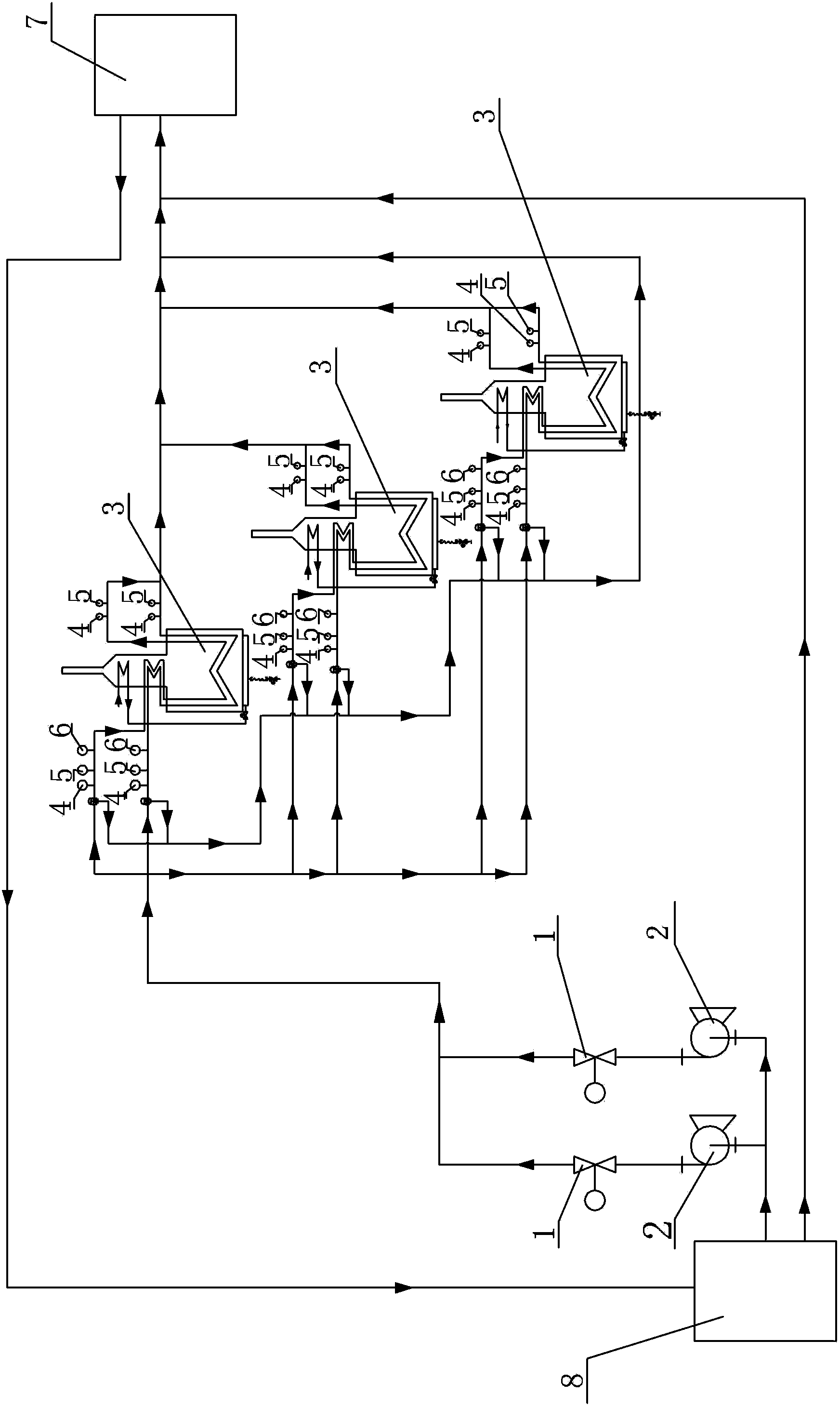
[0007] Specific implementation mode one: combine figure 1 Describe this embodiment. In this embodiment, an anti-condensation system for trough solar thermal power generation includes at least two pump valve systems and at least three boilers 3, and each pump valve system includes a delivery pump 2 and a regulating valve. 1. The heat transfer oil input end of the transfer pump 2 in each set of the pump valve system is used to communicate with the heat transfer oil outlet port of the heat exchange system 8, and the heat transfer oil output of the transfer pump 2 in each set of the pump valve system end is connected with the heat transfer oil inlet port of the corresponding control valve 1, the heat transfer oil outlet port of the control valve 1 in each pump valve system is respectively connected with the heat transfer oil inlet port of each boiler 3, and the heat transfer oil outlet port of each boiler 3 The ends are respectively used to communicate with the mirror field 7 of t...

specific Embodiment approach 2

[0013] Specific implementation mode two: combination figure 1 This embodiment will be described. The boiler 3 in this embodiment is a vertical gas boiler. With this setting, the system has high flexibility, and it is easier to control the flow in the tube, which can be used to compensate the inlet temperature of the mirror field. Others are the same as in the first embodiment.

specific Embodiment approach 3

[0014] Specific implementation mode three: combination figure 1 This embodiment will be described. The control valves 1 in this embodiment are all electric control valves. With such a setting, the flexibility is high, and it is easier to control the flow in the pipe to meet the design requirements and actual needs. Others are the same as in the first or second embodiment.


PUM


Abstract

The invention discloses an anti-condensation system for preventing condensation of heat conduction oil used for groove type solar photo-thermal power generation, and relates to an anti-condensation system.The anti-condensation system aims to solve the problem that the heat conduction oil inside a heating collecting device is naturally cooled and condensed if not being used for a long time or in cold weather after heat of a heat accumulation device in a conventional groove type solar photo-thermal power generation plant is used up. The anti-condensation system comprises at least three boilers and at least two sets of pump valve systems, wherein each set of the pump valve system comprises a conveying pump and an adjusting valve; heat conduction oil input ends of the conveying pumps in the pump valve systems are all used for being communicated with heat conduction oil inlet ends of corresponding adjusting valves; heat conduction oil outlet ends of the adjusting valves in each set of the pump valve system are respectively communicated with the heat conduction oil inlet end of each boiler; and heat conduction oil outlet ends of the boilers are used for being respectively communicated with a mirror field of a groove type solar photo-thermal power generation station. The anti-condensation system is used for preventing the heat conduction oil for the solar photo-thermal power generation from being condensed.

Description

technical field [0001] The invention relates to an anti-condensation system, in particular to an anti-condensation system for preventing condensation of heat transfer oil for trough solar thermal power generation. Background technique [0002] Solar thermal power generation technology has just started in China, and many technologies are in the exploratory stage. Solar power plants have to be started and stopped every day. When the heat of the heat storage system is used up at night, stop the power island (the part of the system connected to the heat exchange system for heat exchange) , if no measures are taken at this time, the heat transfer oil will naturally dissipate heat and cause solidification, especially in cold weather in winter, so that the solar power plant cannot work. Therefore, measures must be taken to avoid this phenomenon. Contents of the invention [0003] The purpose of the present invention is to solve the problem that the heat conduction oil in the heat...

Claims


Application Information

Patent Timeline
Patent Type & Authority Patents(China)
IPC IPC(8): F24J2/46
CPCY02E10/40
Inventor 张秋鸿鞠凤鸣吕光阳崔贤基孙志强冯悦
Owner HARBIN TURBINE
Learn More