Tension and compression-reversing coupling loading testing device for inspecting gas tube structure

A technology of loading a test device and an inflatable tube, which is applied in the direction of applying stable tension/pressure to test the strength of the material and the ductility of the test material to achieve the effect of reducing friction, wide application and simple design

Inactive Publication Date: 2013-01-09
HARBIN INST OF TECH
View PDF4 Cites 16 Cited by
  • Summary
  • Abstract
  • Description
  • Claims
  • Application Information

AI Technical Summary

Problems solved by technology

Inflatable tubes are often subjected to coupled external loads of tension (or compression) and torsion in actual work. The test is the most direct method to evaluate the tensile (or compression) and torsional load-bearing capacity of the inflatable tube structure, but there is no A standard test device can realize the tension-compression-torsional coupling loading test of inflatable tube structures with different lengths and different diameters

Method used


Image

  • Tension and compression-reversing coupling loading testing device for inspecting gas tube structure
  • Tension and compression-reversing coupling loading testing device for inspecting gas tube structure
  • Tension and compression-reversing coupling loading testing device for inspecting gas tube structure

Examples


specific Embodiment approach 1

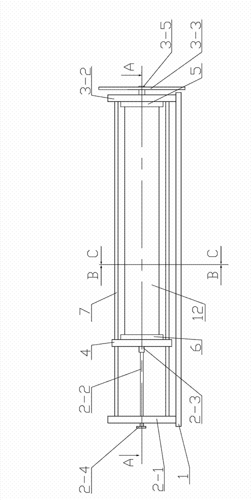
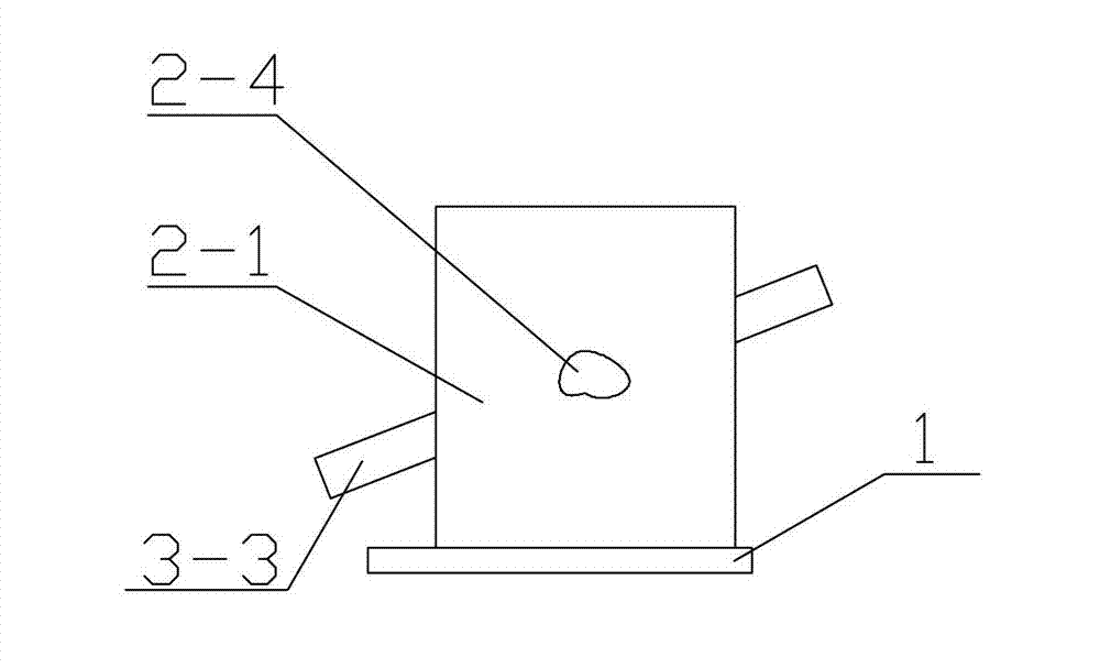
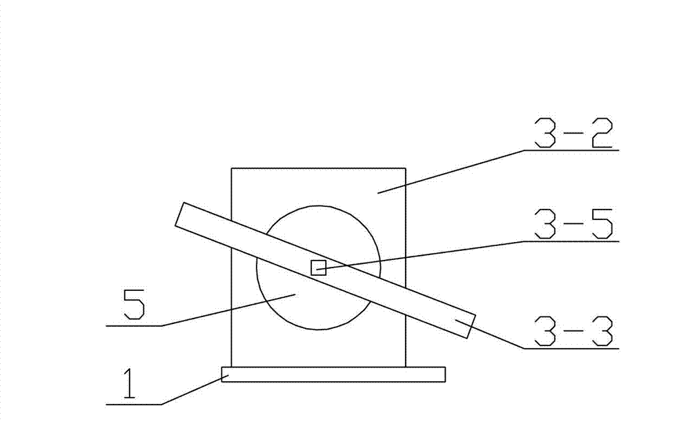
[0015] Specific implementation mode one: combine figure 1 , figure 2 , image 3 , Figure 4 , Figure 5 , Image 6 , Figure 7 , Figure 8 , Figure 9 and Figure 10 Describe this embodiment, the test device in this embodiment includes a fixed platform 1, a tension and compression loading system 2, a torsion loading system 3, a movable baffle 4, a first end cover 5, a second end cover 6 and four Support bar 7, the fixed platform 1 is set horizontally, the tension and compression loading system 2, the torsion loading system 3 and the movable baffle 4 are all arranged on the fixed platform 1, and the movable baffle 4 is vertically arranged on the tension and compression loading system 2 Between the torsion loading system 3, the tension and compression loading system 2 includes a tension and compression loading fixed baffle 2-1, a lead screw 2-2, a load cell 2-3 and a handle 2-4. 3 includes a torsion dial 3-1, a torsional loading fixed baffle 3-2, a torsional loading ro...

specific Embodiment approach 2

[0016] Specific implementation mode two: combination figure 1 , figure 2 , image 3 , Figure 4 , Figure 5 , Image 6 , Figure 7 , Figure 8 , Figure 9 and Figure 10 To describe this embodiment, the torsion dial 3-1 in this embodiment is an annular dial, and a pointer 11 is provided at the midpoint of the top of the torsion loading fixed baffle 3-2. Install the ring dial on the inside of the torsional loading fixed baffle 3-2 (that is, the side of the inflation tube 12) and set it concentrically with the roller 3-4, and the ring dial and the first end cover rotate synchronously, and the pointer 11 is located at the torsion loading fixed At the center position of the top of the baffle plate 3-2, the twist angle of the inflatable tube 12 can be read by the position of the pointer 11 on the twist dial 3-1. Other components and connections are the same as those in the first embodiment.

specific Embodiment approach 3

[0017] Specific implementation mode three: combination figure 1 , figure 2 , image 3 , Figure 4 , Figure 5 , Image 6 , Figure 7 , Figure 8 , Figure 9 and Figure 10 To describe this embodiment, in this embodiment, the four third through holes 10 are all located at the four end corners of the movable baffle 4 . The third through hole 10 provided in this way can make the distance between the inflatable tube 12 and the support rod more reasonable, which is beneficial to the inflatable tube 12 to accurately obtain the data of its tension-compression-torsion coupling loading through the present invention. Other components and connections are the same as those in the first embodiment.


PUM


Abstract

The invention provides a tension and compression-reversing coupling loading testing device for inspecting a gas tube structure, and relates to the tension and compression-reversing coupling loading testing device. The invention aims to solve problems that different testing devices are needed for respectively testing gas tube structures with different lengths and different diameters under a tension and compression-reversing coupling loading test, and a standard testing device is lacked for carrying out the tension and compression-reversing coupling loading test to the gas tube structures with different dimensions. According to the tension and compression-reversing coupling loading testing device, a tension and compression loading system, a reversing loading system and a movable baffle plate are arranged on a fixed platform; the tension and compression loading system comprises a tension and compression loading baffle plate, a lead screw, a force measuring sensor and a handle; the reversing loading system comprises a reversing dial, a reversing loading fixing baffle plate, a reversing loading rod, an idler wheel and a bearing; and the tension and compression loading fixing baffle plate and the reversing loading fixing baffle plate are reversely arranged on two ends of the fixed platform, and fixedly connected with the fixed platform. The tension and compression-reversing coupling loading testing device for inspecting a gas tube structure provided by the invention is applied to the tension and compression-reversing coupling loading test of the gas tube structure.

Description

technical field [0001] The invention relates to a test device, in particular to a tension-compression-torsion coupling loading test device for checking the structure of an inflatable tube. Background technique [0002] The inflatable tube structure is one of the most commonly used load-bearing structures in the inflatable deployment structure. The key to its application is that the inflatable tube structure must have a certain longitudinal tensile or compressive capacity, as well as a circumferential torsional capacity. The so-called longitudinal tensile / compression capacity refers to its ability to resist deformation when the inflatable tube is subjected to tensile / compressive loads; while the hoop torsional capacity refers to its ability to resist deformation when the inflatable tube is subjected to torsional loads. Ability to resist torsional deformation. The smaller the deformation of the inflatable tube, the stronger the bearing capacity of the inflatable tube. Inflat...

Claims


Application Information

Patent Timeline
Patent Type & Authority Applications(China)
IPC IPC(8): G01N3/28G01N3/08
Inventor 林国昌谭惠丰王长国卫剑征岳鹏阳马腾
Owner HARBIN INST OF TECH
Why Eureka
Try Eureka