Dose monitoring system of medical accelerator

A monitoring system and accelerator technology, applied in the direction of dosimeters, etc., can solve the problems affecting the real-time accuracy of dose counting and increasing the unreliability of the system, and achieve the effects of improving monitoring accuracy, low cost, and high transmission efficiency

Active Publication Date: 2013-01-09
SHINVA MEDICAL INSTR CO LTD
View PDF2 Cites 9 Cited by
  • Summary
  • Abstract
  • Description
  • Claims
  • Application Information

AI Technical Summary

Problems solved by technology

In this way, on the one hand, the counting terminal is far away from the signal generating

Method used


Image

  • Dose monitoring system of medical accelerator
  • Dose monitoring system of medical accelerator
  • Dose monitoring system of medical accelerator

Examples


Embodiment 1

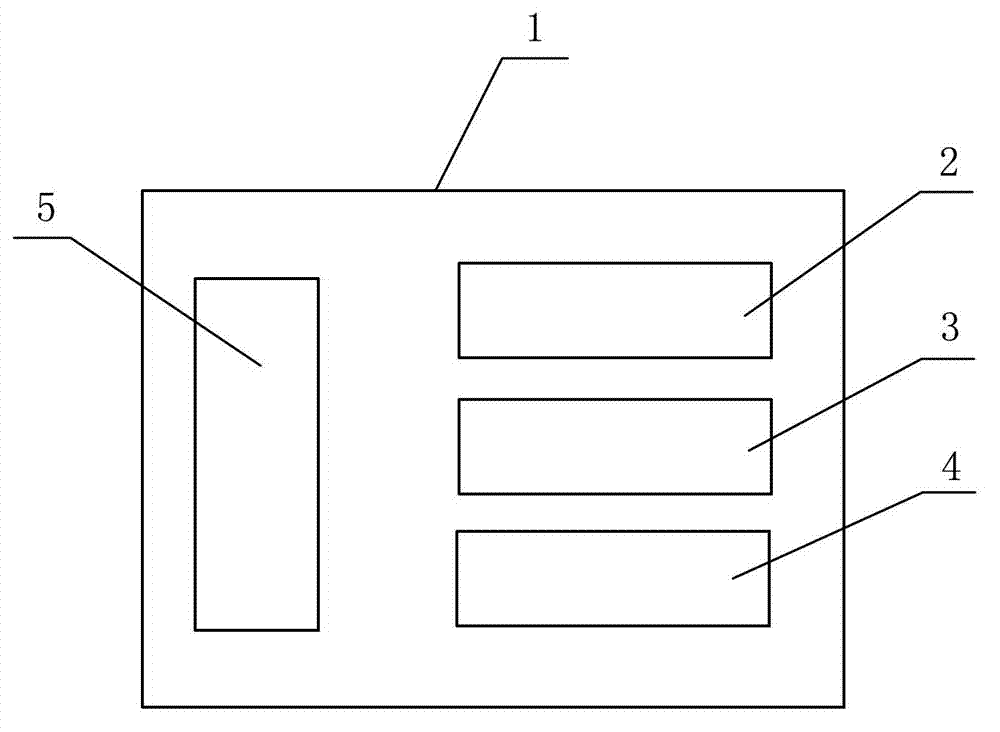
[0027] like figure 1 As shown, the electrical connection power supply assembly 5, the STM main control board 2 and two dose integration boards 3 and 4 are fixed inside the housing 1, and the housing 1 adopts an all-aluminum shielding housing.

[0028] The power supply assembly 5 is provided with a power plug connected to the outside of the casing, and the output terminals of the power supply assembly 5 are respectively connected to the power terminals of the STM main control board 2 and the two dose integration boards 3 and 4 .

[0029] The input ends of the two dose integration boards 3 and 4 are respectively provided with interfaces for connecting and receiving the current signal generated by the dose monitoring ionization chamber, and their output ends are respectively connected to the input end of the STM main control board 2 and the output end of the STM main control board 2 The communication interface provided on the shell 1 is connected through the CAN bus, and is used ...

Embodiment 2

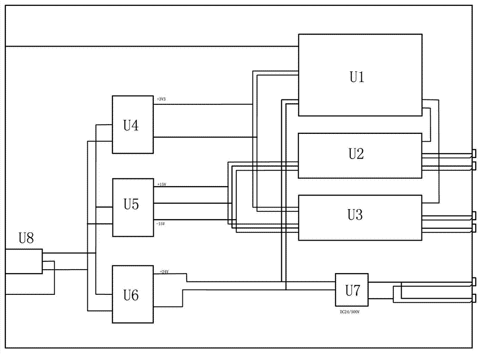
[0037] like Figure 4 As shown, on the basis of Embodiment 1, a signal adapter board U13 and a -500V sampling board U14 are also arranged inside the housing 1, and the output terminals of the power supply assembly 5 are respectively connected to the STM main control board U1, the signal adapter board U13, the ionization The power supply of the room and the power terminals of the two dose integration boards U2 and U3, the input terminal of the signal adapter board U13 are respectively connected to the output terminals of the two dose integration boards U2, U3 and the -500V sampling board U14, and the output of the signal adapter board U13 The terminal is connected to the input terminal of the STM main control board U1, and the input terminal of the 500V sampling board U14 is set to connect to the -500V signal of the ionization chamber.

[0038] The power supply assembly 5 includes the module power supply U4-U7, U12 and the filter unit U8, the power plug is connected to the inpu...


PUM


Abstract

The invention particularly relates to a dose monitoring system of a medical accelerator, which is used for accurate dose of medical accelerator output dose. The dose monitoring system is characterized in that a power supply assembly (5), a scanning tunneling microscope (STM) main control plate (2) and two dose integration plates (3 and 4) are fixedly arranged in a shell (1) and are electrically connected, the shell (1) is a full-aluminum shielding shell, the input ends of the two dose integration plates (3 and 4) are respectively provided with interfaces and are used for connecting and receiving a current signal generated by a dose monitoring ionization chamber, the output ends of the dose integration plates (3 and 4) are respectively connected with the input end of the STM main control plate (2), the output end of the STM main control plate (2) is connected with a communication interface via a controller area network (CAN) bus and is used for data transmission with a main control system of the medical accelerator by utilizing CAN communication, and the commutation interface is arranged on the shell (1). By the dose monitoring system, the influence of external electromagnetic interference and mutual interference prior to internal components on the dose monitoring system is effectively reduced, the dose monitoring accuracy is improved, and the stability of the main control system of the medical accelerator is improved.

Description

technical field [0001] The invention is mainly used for accurate dose output to a medical accelerator, and in particular relates to a dose monitoring system of a medical accelerator. Background technique [0002] The original dose system generally only converts the current signal generated by the dose monitoring ionization chamber into a digital pulse signal. These digital pulse signals are counted by the main control system of the medical accelerator. In this way, on the one hand, the counting terminal is far away from the signal generating parts, which increases the unreliability of the system; Real-time accuracy of dose counting. Contents of the invention [0003] Based on the above deficiencies in the prior art, the technical problem to be solved by the present invention is to provide a dose monitoring system for a medical accelerator that can independently perform dose counting, has less signal disturbance, and has high stability. [0004] The technical solution ad...

Claims


Application Information

Patent Timeline
IPC IPC(8): G01T1/02
Inventor 纪东泽成希革秦嘉川
Owner SHINVA MEDICAL INSTR CO LTD
Why Eureka
Try Eureka