Eureka AIR delivers breakthrough ideas for toughest innovation challenges, trusted by R&D personnel around the world.

Transformer

A transformer and heat sink technology, applied in the field of transformers, can solve problems such as poor power supply quality and no access to the third harmonic, and achieve the effects of improving external heat dissipation, reducing costs, and reducing usage

Inactive Publication Date: 2013-01-09
沈阳天维电气设备制造有限公司
View PDF6 Cites 0 Cited by
  • Summary
  • Abstract
  • Description
  • Claims
  • Application Information

AI Technical Summary

Problems solved by technology

[0009]7. The wall thickness of the radiator is smaller than that of the oil tank of the main body of the transformer, so the radiator and the oil tank of the main body of the transformer cannot be made of steel plates of the same specification. The resulting thermal stress is also different, and the oil tank and radiator of the main body of the existing transformer have an integrated structure, and there is no buffer device between the two, so the processing technology is very complicated
[0010]8. Considering the expansion of the transformer oil in the oil tank after being heated in the existing transformer structure, the radiator needs to bear a certain expansion coefficient, and after repeated expansion and contraction After several years of stress, the hidden dangers of seepage and oil leakage will become larger and larger
[0011]9. The existing box-type substations are generally arranged in the shape of a mesh or a font, with a separate transformer room, and all the equipment is on the ground, occupying a lot of space big, ugly
[0012]10. The connection group of the existing transformer is generally Y, yn0. This connection method has no path for the third harmonic, and the power supply quality is not good

Method used


Image

  • Transformer
  • Transformer
  • Transformer

Examples


Embodiment Construction

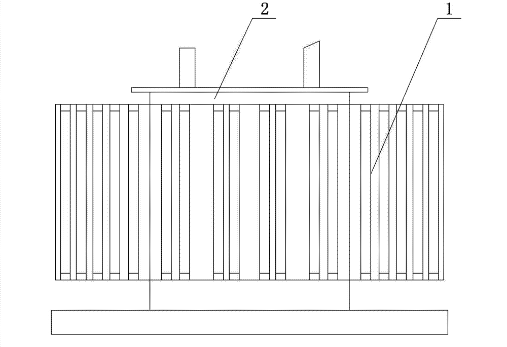
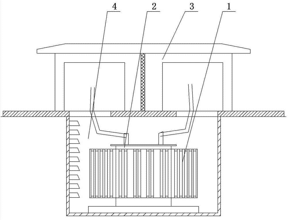
[0030] As shown in the figure, the present invention includes a transformer main body 2 and a radiator 1 surrounding the transformer main body 2. The transformer main body 2 is arranged in a box in the middle of the radiator 1. There is a main cavity between the inner wall of the box and the main body of the transformer, and the outer wall of the box and the main cavity. There is a cooling cavity between the inner walls of the radiator; transformer oil is arranged in the main cavity, and water is arranged in the cooling cavity.

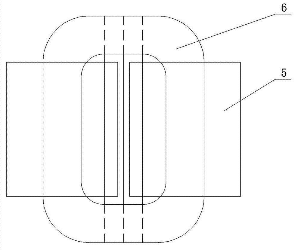
[0031] The main body of the transformer 2 adopts a three-phase three-dimensional wound core. The three-phase three-dimensional wound core adopts the D, yn11 connection group, the third harmonic has a path, and the short-circuit resistance is stronger than that of the Y, yn0 connection group transformer, and the D, yn11 connection group transformer has a certain filtering effect; therefore The quality of power supply is stable and the ability to re...


PUM


Abstract

The invention provides a transformer which is high in safety and radiation and low in cost and relates to modification of a transformer structure. The transformer comprises a transformer body and a radiator around the transformer body and is structurally characterized in that the transformer body is arranged in a box in the middle of the radiator, a main cavity is arranged between the inner wall of the box and the transformer body, a radiating cavity is arranged between the outer wall of the box and the inner wall of the radiator, transformer oil is reserved in the main cavity, and water is reserved in the radiating cavity.

Description

technical field [0001] The present invention relates to the improvement of transformer structure. Background technique [0002] Existing transformers can be divided into three-phase three-column type and three-phase five-column type according to the iron core structure, and they are all arranged in a plane. The existing transformers have the following disadvantages. [0003] 1. The length of the core magnetic circuit is different, and the no-load current ABC three phases are different. [0004] 2. The iron core sheets need to be stacked manually after slitting and cross cutting, which takes a lot of time and has a lot of human interference. [0005] 3. Since the iron chip is an oriented silicon steel sheet, it is necessary to adopt a fully inclined 45° joint at the turning of the magnetic circuit, which is a high-resistance area of ​​the magnetic circuit, and there is a distortion of the magnetic flux, which will increase the noise of the transformer to a certain extent A...

Claims


Application Information

Patent Timeline
Patent Type & Authority Applications(China)
IPC IPC(8): H01F30/12H01F27/16H01F27/24
Inventor 王瑞林王越龙
Owner 沈阳天维电气设备制造有限公司
Why Eureka
Eureka Blog
Learn More