Moire magnification device

A corrugated magnification and component technology, applied in printing, lens, banknote authenticity inspection, etc., can solve problems such as difficult and multi-color effects, and achieve the effect of avoiding the need for mutual registration

Inactive Publication Date: 2013-01-09
DE LA RUE INT LTD
View PDF21 Cites 10 Cited by
  • Summary
  • Abstract
  • Description
  • Claims
  • Application Information

AI Technical Summary

Problems solved by technology

[0008] However, a problem with known devices is that it is very difficult to achieve multicolor effects in which two or more images of different colors are obtained

Method used


Image

  • Moire magnification device
  • Moire magnification device
  • Moire magnification device

Examples


Embodiment

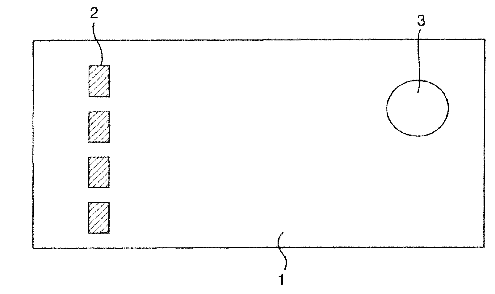
[0085] Assuming Figure 2 and Figure 10 The structure consists of a microlens 22 with a focal length f of 40 μm or 0.04 mm. In addition, it is assumed that both the microlens and the support substrate 20 are composed of a material having a refractive index n of 1.5. Thus, it follows that the bottom diameter D of the lens is defined by the following expression: D≤f*2(n-1), therefore D≤0.04*2(1.5-1), resulting in D≤0.04mm.

[0086] A value of 0.035mm can then be chosen for D, and a value of 0.04mm (along each axis) for lens spacing B, so that the lens array has an f / # number close to 1 with reasonable close packing (close packing) (the lens gap is 5 μm).

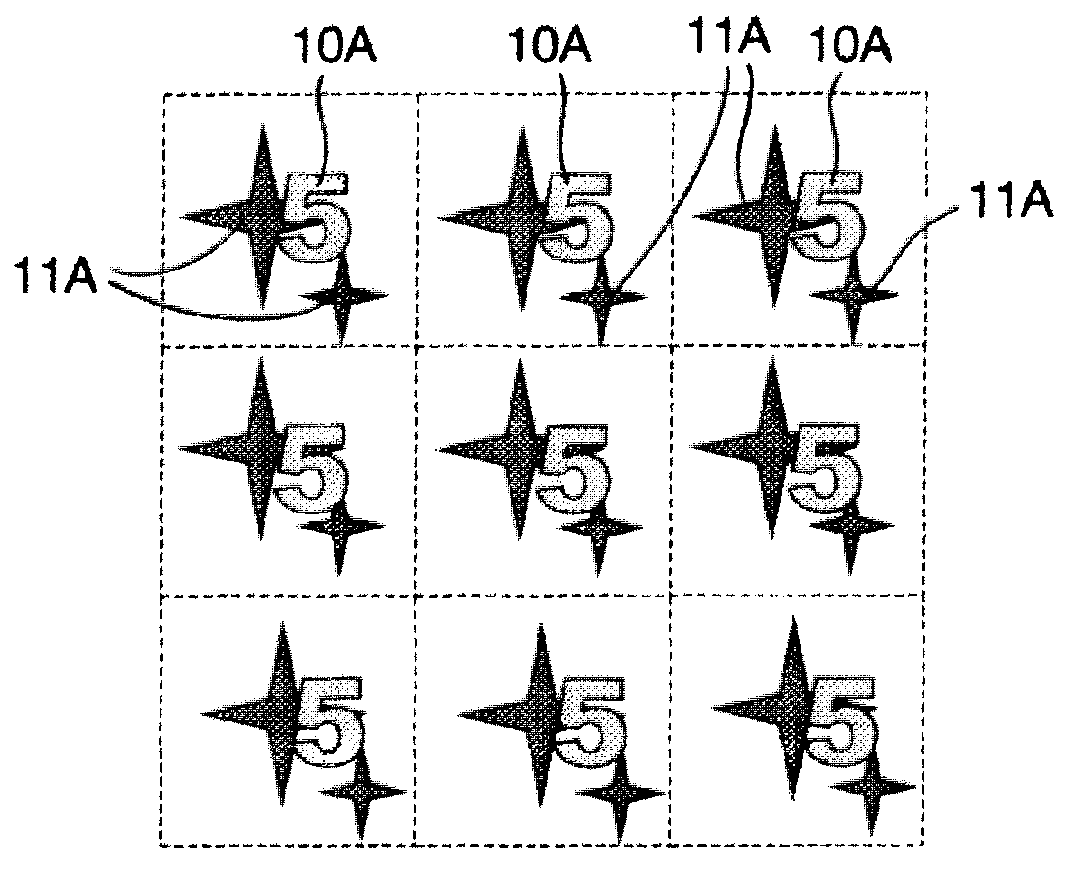
[0087] In the first embodiment, it is assumed that the first image array 10 is required to be located at 2 mm behind the surface plane of the substrate, and the second image array 11 is located at 6 mm behind the surface plane, (note that by definition, the surface plane behind images are virtual, and a more detailed analys...


PUM


Abstract

A moire magnification device comprises a transparent substrate (20) carrying: i) a regular array (22) of micro-focusing elements on a first surface, the focusing elements defining a focal plane; ii) a corresponding first array (10) of microimage elements in a first colour and located in a plane substantially coincident with the focal plane of the focusing elements; and, iii) a corresponding second array (11) of microimage elements, in a second colour different from the first colour, and located in a plane substantially coincident with the focal plane of the focusing elements. The pitches of the micro-focusing elements (22) and first and second arrays (10, 11) of microimage elements and their relative locations are such that the array of micro-focusing elements cooperates with each of the first and second arrays of microimage elements to generate respective magnified versions of the microimage elements of each array due to the moire effect and such that the magnified version of the first array of microimage elements is viewed against a background defined by the magnified version of the second array of microimage elements, the magnified version of the first array of microimage elements exhibiting movement relative to the background when the device is tilted, and wherein the pitch mismatch between the arrays is chosen such that the magnified version of the elements of the first array appears above or below the magnified version of the elements of the second array.

Description

technical field [0001] The present invention relates to moirémagnification devices, such as security devices, for example for use on security documents and other items of value, such as banknotes, cheques, passports, identity cards, certificates of authenticity, revenue stamps and others for insuring value or proving personal identity document. The invention also relates to optical devices used in packages and the like. Background technique [0002] For several years, ripple amplification has been used as the basis for safety devices. Several examples are described in WO-A-94 / 27254 and EP-A-1695121. In such devices, a regular array of microfocusing elements defining a focal plane is arranged above a corresponding array of image elements lying in a plane substantially aligned with the focal plane of the focusing elements. The pitch or periodicity of the array of picture elements is chosen to differ from the pitch or period of the focusing elements by a small factor, and th...

Claims


Application Information

Patent Timeline
Patent Type & Authority Applications(China)
IPC IPC(8): B42D15/10G07D7/00
CPCG02B3/0056G07D7/0006G07D7/2066B42D2035/44B42D25/342B42D2035/20B42D15/002B42D25/324B42D25/351G07D7/003G07D7/207
Inventor B·W·霍姆斯
Owner DE LA RUE INT LTD
Why Eureka
Try Eureka