Passive power generation system

a power generation system and passive technology, applied in the direction of transformer/inductance circuit, digital storage, inductance, etc., can solve the problem that tesla failed to discover and solve the problem of providing practical magnification

Inactive Publication Date: 2013-12-17
ENERGY MAGNIFICATION
View PDF15 Cites 8 Cited by
  • Summary
  • Abstract
  • Description
  • Claims
  • Application Information

AI Technical Summary

Problems solved by technology

Notwithstanding, Tesla failed to discover and solve the problem of providing practical magnification of electricity or energy and local recovery of the magnified electricity or energy.

Method used


Image

  • Passive power generation system
  • Passive power generation system
  • Passive power generation system

Examples


Embodiment Construction

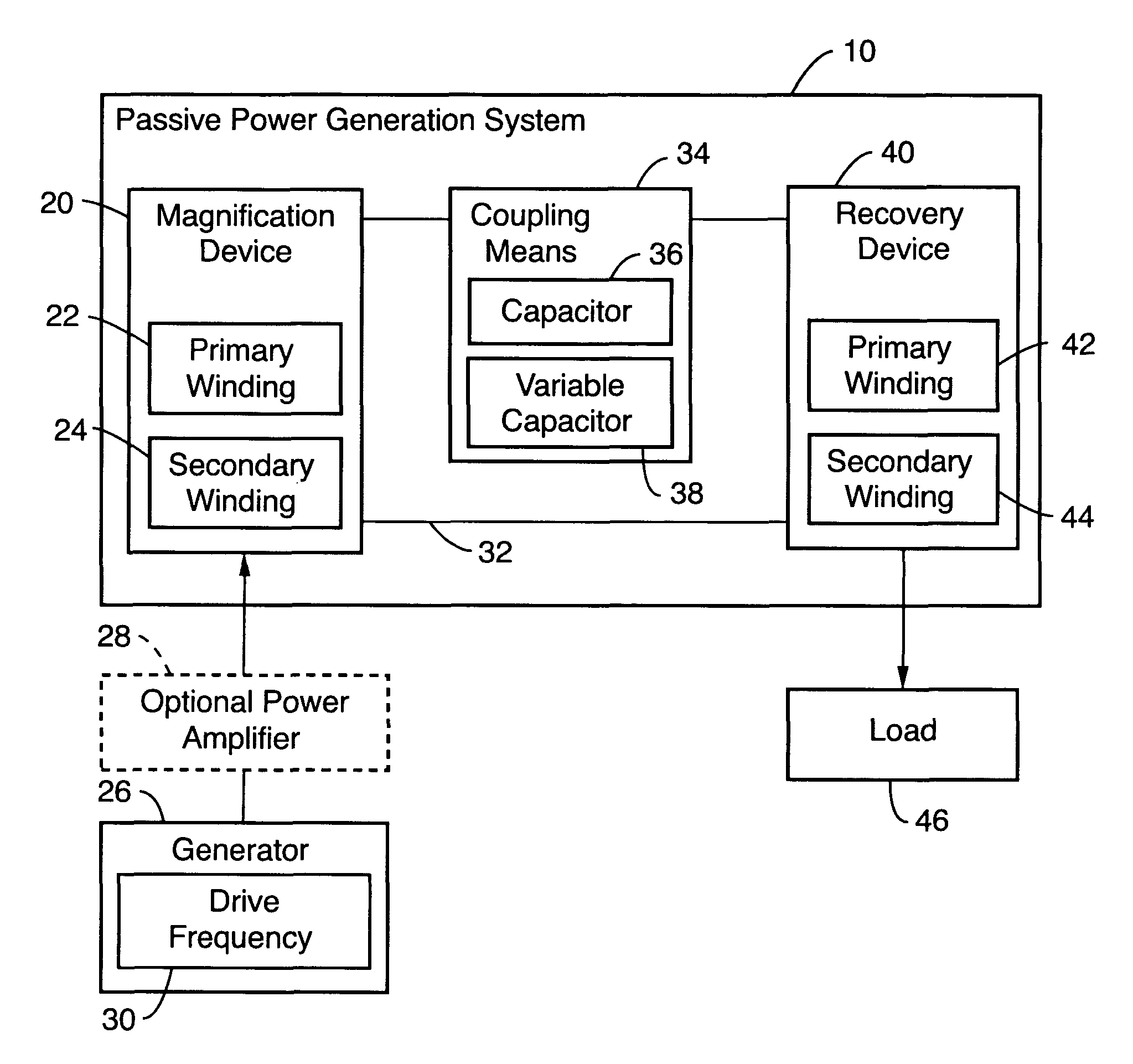
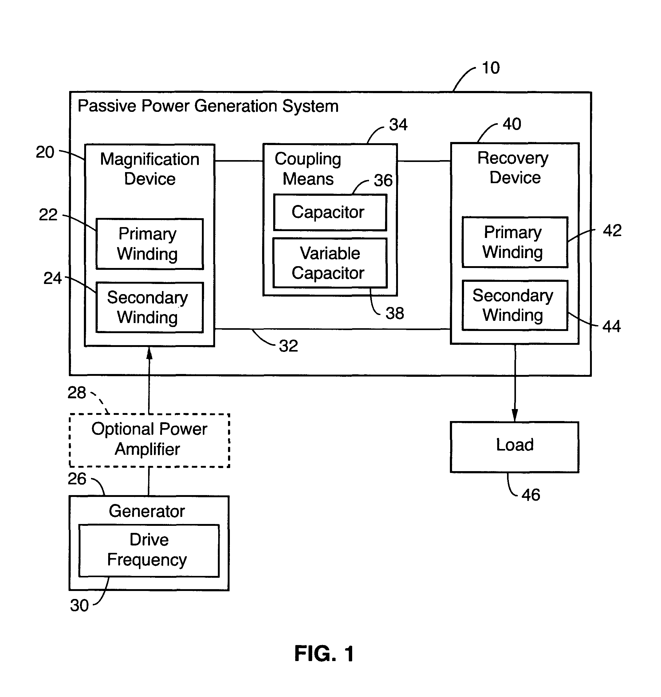
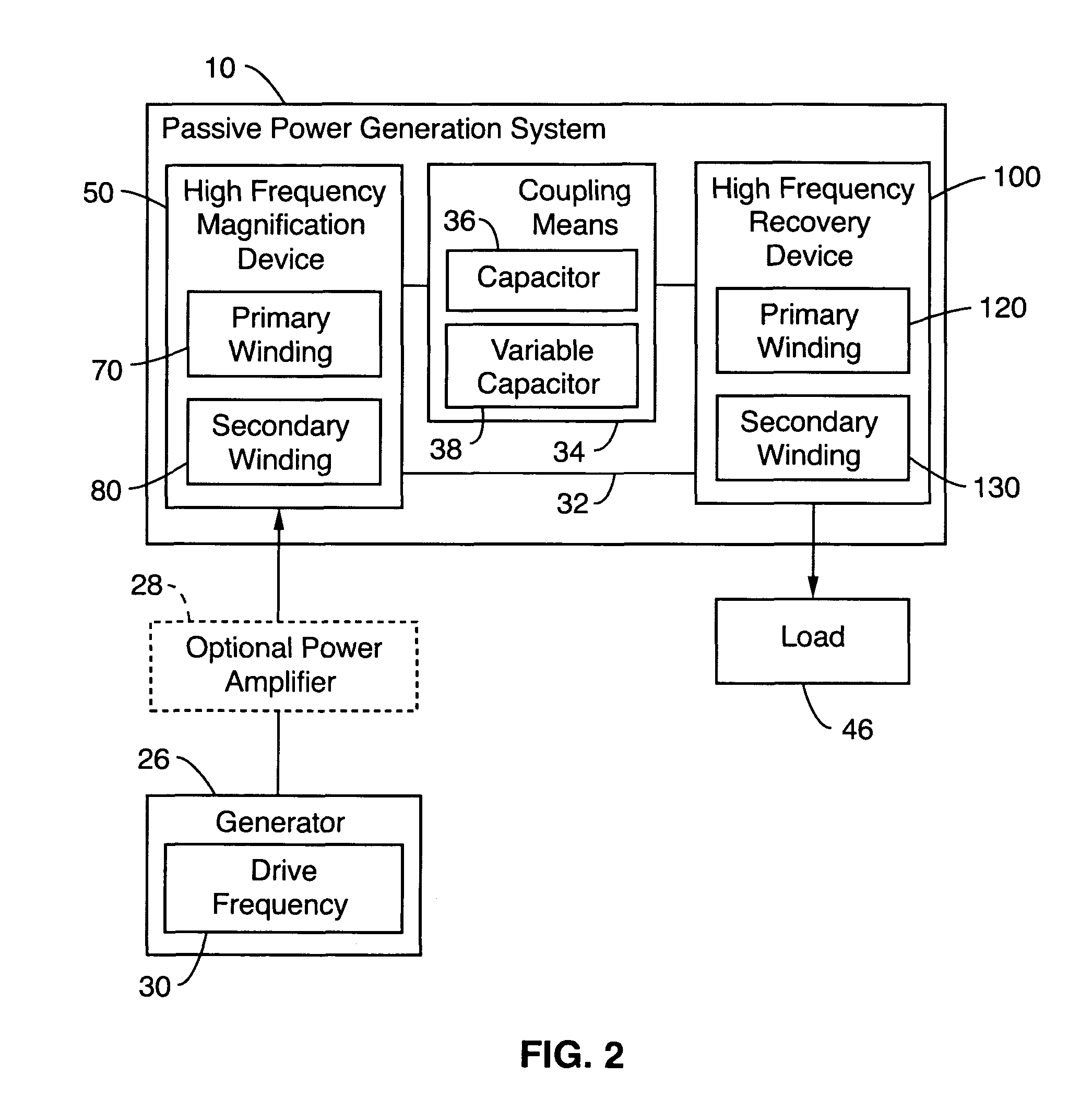
[0070]The following introductory material is provided before delineating a detailed description of a passive power generation system 10 for assisting in a clear understanding of the passive power generation system.

[0071]Introductory Material

[0072]The passive power generation system 10 has roots in the known laws of physics and is a novel, unobvious, and useful category of an electrical system that uses Faraday's Law and the principle of the conservation of energy in a novel, unobvious, and useful manner. Faraday's law of induction deals with the idea of “fields.” A field is a concept used by physics to avoid action at a distance. If a field is present, the field is acting on a particle (such as an electron) and explains particle motions due to the field present at its location. “Flux” is a particular field's strength over some unit area. When we map the field into three-dimensional space we have a flux over some two-dimensional cross-section of that space. Faraday's law states that ...


PUM

PropertyMeasurementUnit
speedaaaaaaaaaa
power frequenciesaaaaaaaaaa

Abstract

A passive power generation system comprised of a magnification device for magnifying energy and a recovery device operatively coupled to the magnification device for recovering at least a portion of the magnified energy and a method for making the passive power generation system for magnifying and recovering energy.

Description

CROSS-REFERENCE TO RELATED APPLICATIONS[0001]This application claims priority under 35 USC Section 119(e) to U.S. Provisional Patent Application No. 61 / 206,086, filed Jan. 27, 2009 the entire disclosure of which is incorporated herein by reference.FIELD OF THE INVENTION[0002]This invention relates generally to passive power generation systems and, in particular, to a passive power generation system comprised of a magnification device for magnifying electricity or energy, a recovery device for recovering at least a portion of the magnified electricity or energy, and a coupling between the two devices. This invention also relates to methods for making and using the passive power generation system which, in one aspect, includes a use for local power recovery applications. Additionally, this invention also relates to standalone uses for the magnification device.BACKGROUND OF THE INVENTION[0003]Energy resources and the conservation of energy are at the forefront of today's most critical ...

Claims


Application Information

Patent Timeline
Patent Type & Authority Patents(United States)
IPC IPC(8): H01F27/42H01F38/00
CPCH01F27/325H01F30/06
Inventor GRIMES, SEAN N.
Owner ENERGY MAGNIFICATION
Why Eureka
Try Eureka