
Compact illumination and magnification device

a compact, magnification technology, applied in lighting and heating apparatus, printing, instruments, etc., can solve the problems of affecting the emitted light, and increasing the likelihood that the emitted light may disturb others in the vicinity,

Inactive Publication Date: 2009-08-18
VERSO BRAND HLDG LLC
View PDF73 Cites 8 Cited by
  • Summary
  • Abstract
  • Description
  • Claims
  • Application Information

AI Technical Summary

Benefits of technology

"The present invention provides a portable device that can uniformly illuminate and magnify words, images, or other information on a surface, while minimizing the amount of light transmitted beyond the illuminated surface. The device has a light source, a light transmitting body, and a magnifying lens. The light transmitting body is made of a light conductive material that transmits light uniformly through the body. The magnifying lens is positioned adjacent to a tapering side edge of the light transmitting body or within the light transmitting body. The light source may be one or more light bulbs, and the light transmitting body and / or the magnifying lens may have recesses to receive the light bulbs. The device is secured to a housing, which is positioned to allow the light source to emit light into the thicker edge of the light transmitting body and / or the magnifying lens. The technical effects of the invention include improved portability, uniform illumination, and magnification of information on surfaces."

Problems solved by technology

A disadvantage of these devices is that the point light source fails to provide substantially uniform illumination because areas closer to the light source are more brightly lit.
Moreover, any attempt to provide adequate lighting for the entire magnified area by increasing the lumens of the light bulb increases the likelihood that the emitted light may disturb others in the vicinity, especially because the single bulb also emits light that is not diffused.
As a result, the light can disadvantageously reflect off the viewed surface to the surroundings.
Although a Fresnel lens allows the magnifying lens to be significantly thin, a known disadvantage of using a Fresnel lens is that the quality of the image is not nearly as good as that from a continuous lens, such as the convex lenses used in the devices previously discussed above.
In addition, like the point light source of the devices above, the elongate light source suffers from the disadvantage of non-uniform lighting, because areas closer to the light source are more brightly lit.
Moreover, this device fails to effectively utilize all of the light available for illuminating the magnified area, thus decreasing its utility.

Method used


Image

  • Compact illumination and magnification device
  • Compact illumination and magnification device
  • Compact illumination and magnification device

Examples


Embodiment Construction

[0021]The following presents a detailed description of a portable device that facilitates the viewing of words, images, or other information on a surface, particularly in dark or poorly lit environments. The present invention directs light from a light source uniformly onto the surface to illuminate and to magnify the words, images, or other information on the surface, while minimizing or reducing the amount of light transmitted beyond, or away from, the illuminated surface.

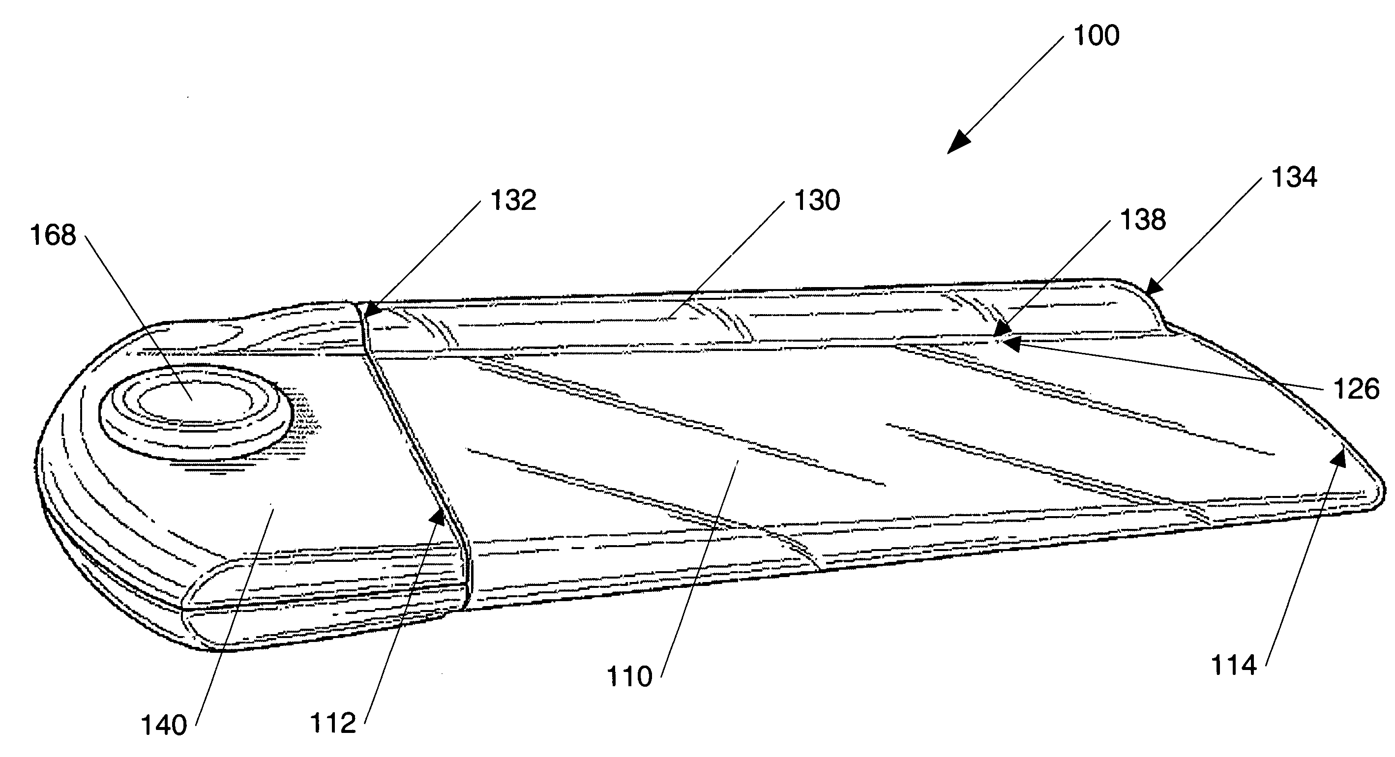
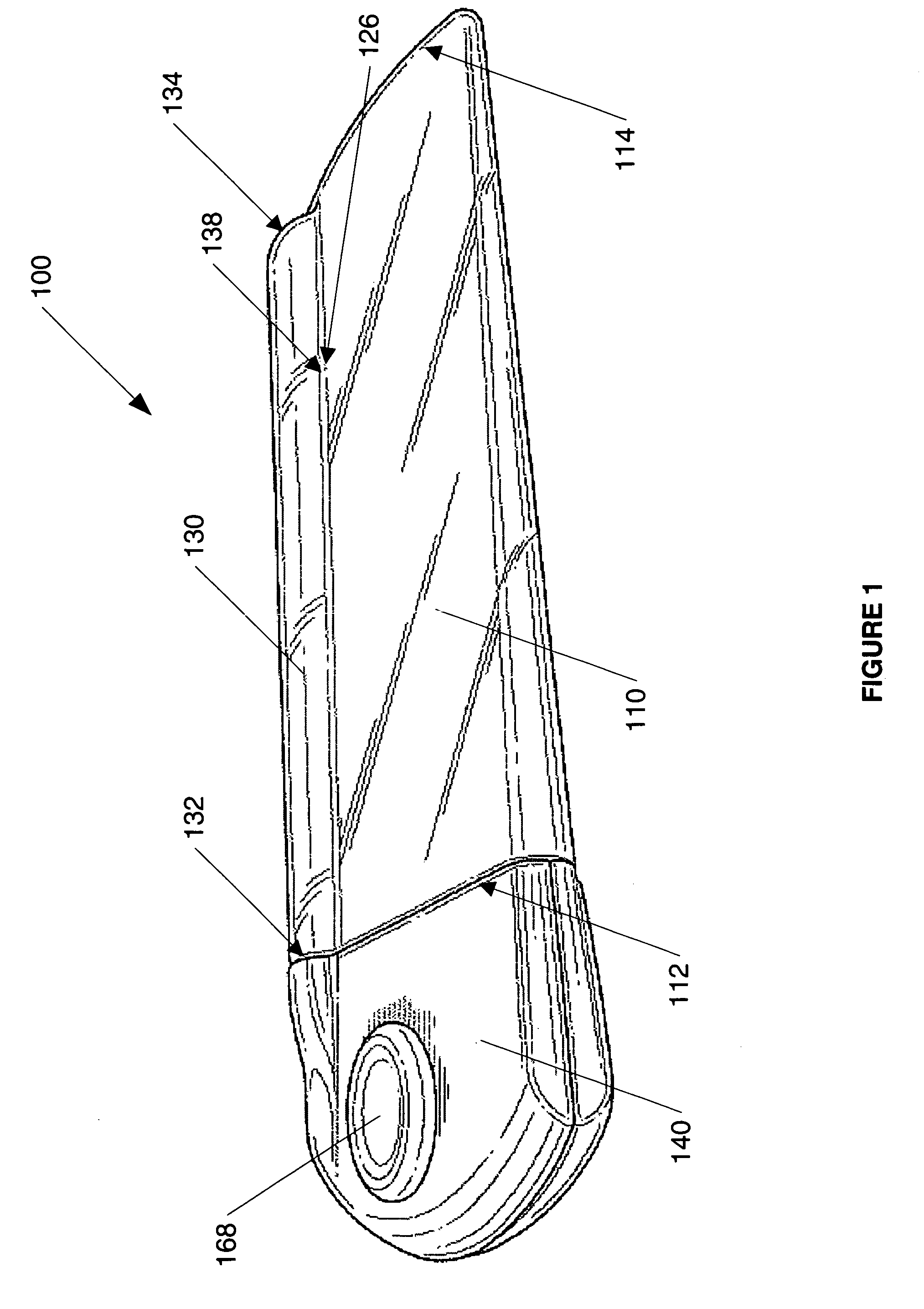
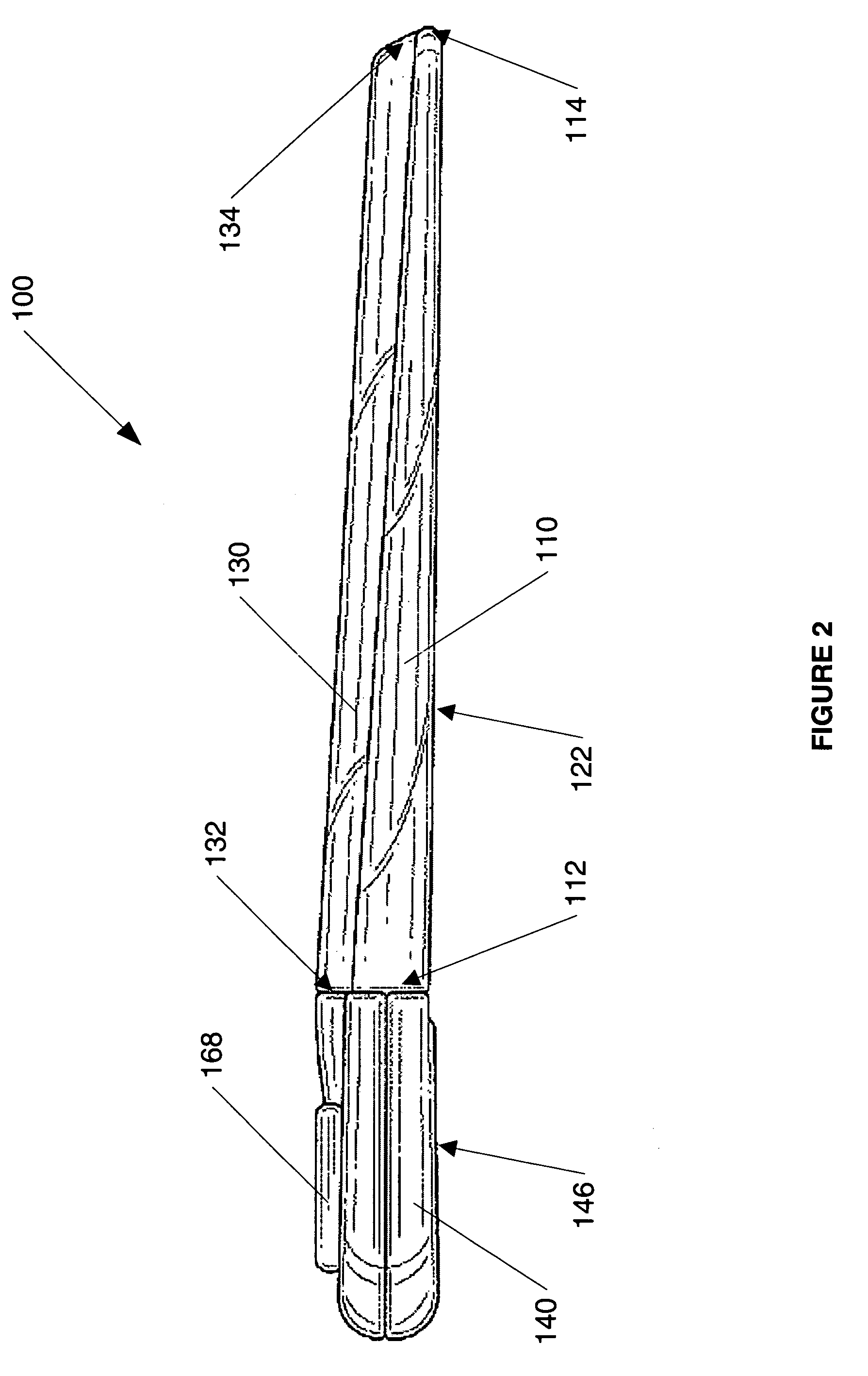
[0022]Referring to the accompanying drawings, FIG. 1 illustrates a front perspective view of a compact illumination and magnification device 100 in accordance with an exemplary embodiment of the present invention. The illumination and magnification device 100 has a light transmitting body 110, a magnifying lens 130, and a housing 140.

[0023]The light transmitting body 110 is dimensioned and configured to be portable and to overlie the surface, or a part of the surface, to be illuminated. Preferably, the light tran...


PUM


Abstract

A compact and portable device uniformly illuminates and magnifies the words, images, or other information on a surface, such as the words on a page of a book, while minimizing the amount of light transmitted beyond or away from the illuminated surface. The device employs a light transmitting body formed of a transparent light conductive material and a magnifying lens. The device also employs a housing with a light source and a power source for powering the light source. To receive and deflect light from the light source onto the underlying surface, the light transmitting body is configured to have a wedge shape tapering from a thicker edge to a thinner edge. The wedge-shaped light transmitting body and the magnifying lens may be integrally formed to allow seamless transmission of light between the light transmitting body and the magnifying lens.

Description

BACKGROUND OF INVENTION[0001]The present invention relates generally to a portable illumination and magnification device, and more particularly to a portable device adapted for uniformly illuminating and magnifying words, images, or other information on a surface, such as a page of a book, while minimizing the amount of light transmitted beyond, or away from, the illuminated surface.DESCRIPTION OF RELATED ART[0002]Portable illumination and magnification devices are known and have various configurations. Such devices are normally used to improve lighting and. facilitate viewing of printed materials, such as restaurant menus, theatre programs, or car maps with small type fonts, in dark or poorly lit environments.[0003]Several commercially available devices employ a convex magnifying lens, which is usually rectangular, with a single light bulb positioned near the middle of the bottom edge of the magnifying lens, the light bulb being powered by a simple switch. A disadvantage of these d...

Claims


Application Information

Patent Timeline
Patent Type & Authority Patents(United States)
IPC IPC(8): G03B29/00F21L4/00
CPCG02B25/02G02B25/005
Inventor BENNETT, JR., JAMES F.
Owner VERSO BRAND HLDG LLC
Learn More