Optical pulse amplication apparatus and method
- Summary
- Abstract
- Description
- Claims
- Application Information
AI Technical Summary
Benefits of technology
Problems solved by technology
Method used
Image
Examples
Embodiment Construction
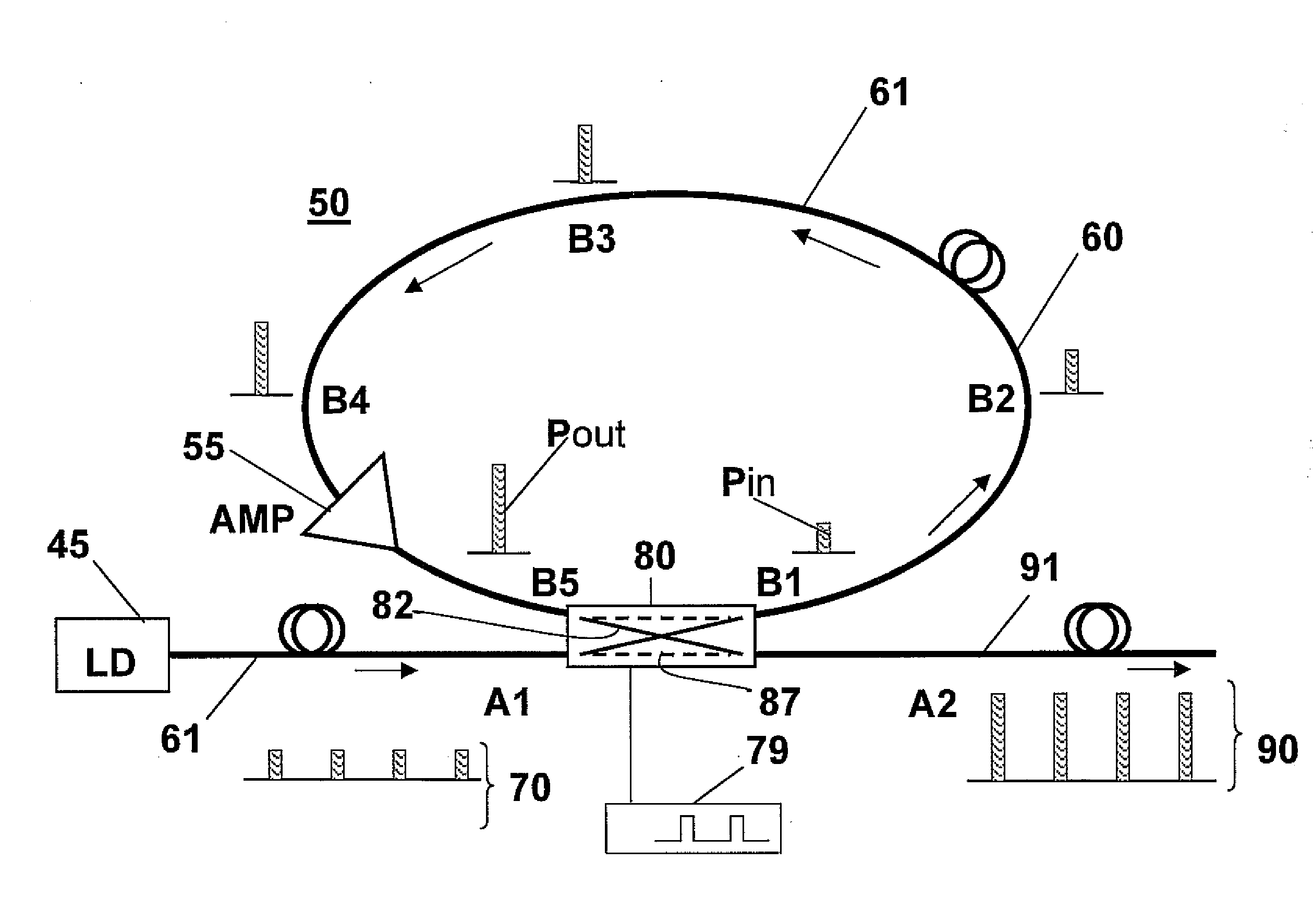
[0027]FIG. 3 depicts a pulse amplification apparatus 50 according to an example embodiment of the present invention. In the apparatus depicted in FIG. 3, an optical amplifier 55 is positioned anywhere within a re-circulating fiber loop 60 to amplify optical pulses “P” propagating inside the fiber loop 60. Hereinafter, the term “fiber loop” may be used interchangeably with terms such as “fiber optic loop”, “optical loop”, or “optic loop”. Fiber loop 60 includes at least fiber 61, optical amplifier 55, and an optical switch 80. In one embodiment, the re-circulating fiber loop 60 is of a length “L”, which length is designed according to the optical pulse period (frequency) of the input optical pulse stream 70 and a desired optical pulse amplification gain criteria, as will be described in greater detail herein below. In one non-limiting embodiment, the length “L” of the fiber loop is shorter than the distance an optical pulse inside the re-circulating fiber loop 60 travels during a rep...
PUM
 Abstract
Description
Claims
Application Information
 - R&D
- Intellectual Property
- Life Sciences
- Materials
- Tech Scout
- Unparalleled Data Quality
- Higher Quality Content
- 60% Fewer Hallucinations
Browse by: Latest US Patents, China's latest patents, Technical Efficacy Thesaurus, Application Domain, Technology Topic, Popular Technical Reports.
© 2025 PatSnap. All rights reserved.Legal|Privacy policy|Modern Slavery Act Transparency Statement|Sitemap|About US| Contact US: help@patsnap.com


