Optical pulse amplication apparatus and method

a technology of optical pulses and amplifiers, applied in the field of optical signal processing and amplification, can solve the problems of insufficient peak power of optical pulses generated by laser diodes or light-emitting diodes, and the series of optical pulses generated by laser diodes (lds), etc., and achieve the effects of reducing the average input power, reducing the total combined or accumulated gain, and delay in amplifier saturation

Inactive Publication Date: 2011-10-11
INT BUSINESS MASCH CORP
View PDF39 Cites 9 Cited by
  • Summary
  • Abstract
  • Description
  • Claims
  • Application Information

AI Technical Summary

Benefits of technology

[0007]The present invention is directed to a pulse amplification apparatus and methodology employing an optical amplifier that amplifies optical pulses through a re-circulating fiber loop and launches the amplified optical pulses through an optical switch. By careful arrangement of optical pulses in a graded series inside the apparatus and by taking advantage of the low average input power (averaged over the photon lifetime) to an optical amplifier of moderate gain, for example, a series of narrow optical pulses will experience a significantly higher total combined or accumulated gain, which would normally require a series of cascaded optical amplifiers of moderate gain or some expensive high-gain optical amplifiers. Thus, the apparatus emulates the effect of multiple optical signal amplifiers, however, by adopting a methodology of lowering average input power, through creating a graded pulse series, for delayed amplifier saturation.

Problems solved by technology

Normally, a series of optical pulses generated by a laser diode (LD), or a light-emitting diode (LED), may not have the intensity sufficient for most of the applications such as, for example, medical devices.
It is apparent that, for some applications, this apparatus 10 may not provide optical pulses with sufficient peak power.
However, such an apparatus 20 has drawbacks which may include, for example, the high cost associated with using multiple amplifiers and an early point of saturation, e.g., at +11 dBm output, such as shown in FIG. 2B, although some un-proportionally expensive amplifiers may provide a higher saturated output power.

Method used


Image

  • Optical pulse amplication apparatus and method
  • Optical pulse amplication apparatus and method
  • Optical pulse amplication apparatus and method

Examples


Embodiment Construction

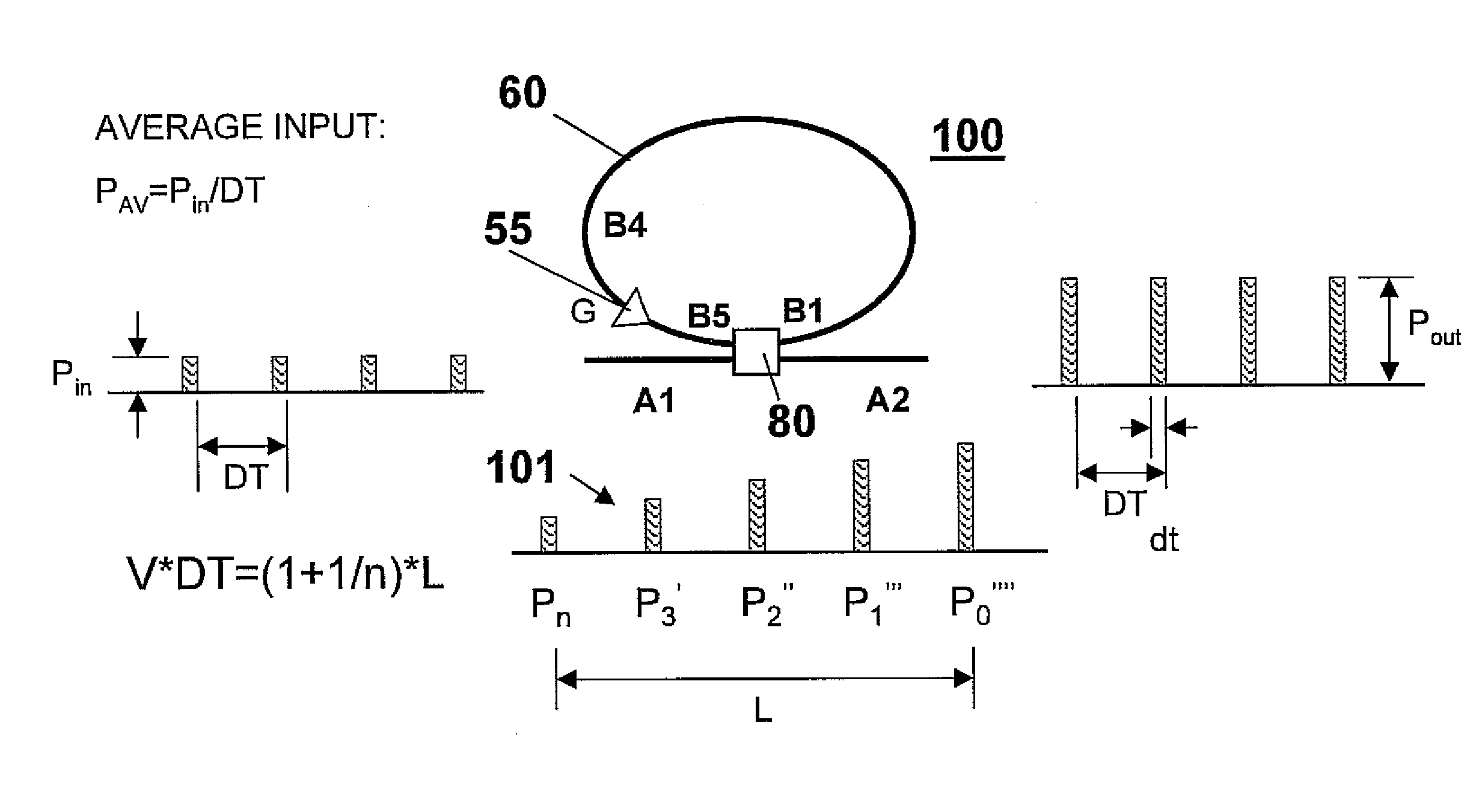
[0027]FIG. 3 depicts a pulse amplification apparatus 50 according to an example embodiment of the present invention. In the apparatus depicted in FIG. 3, an optical amplifier 55 is positioned anywhere within a re-circulating fiber loop 60 to amplify optical pulses “P” propagating inside the fiber loop 60. Hereinafter, the term “fiber loop” may be used interchangeably with terms such as “fiber optic loop”, “optical loop”, or “optic loop”. Fiber loop 60 includes at least fiber 61, optical amplifier 55, and an optical switch 80. In one embodiment, the re-circulating fiber loop 60 is of a length “L”, which length is designed according to the optical pulse period (frequency) of the input optical pulse stream 70 and a desired optical pulse amplification gain criteria, as will be described in greater detail herein below. In one non-limiting embodiment, the length “L” of the fiber loop is shorter than the distance an optical pulse inside the re-circulating fiber loop 60 travels during a rep...


PUM


Abstract

A method and apparatus for producing a series of amplified optical pulses from a series of input optical pulses including creating a set of local optical pulses from a series of input optical pulses, the set of local optical pulses having different amplitudes arranged in a graded order. The set of local optical pulses are amplified by an optical amplifier to form a significantly amplified first local optical pulse that is removed from the set of local optical pulses and output. The method successively removes the significantly amplified first local optical pulse, re-creates the set of local optical pulses by adding a new optical pulse to the end of the set of local optical pulses; and routes the recreated set of local optical pulses back to the input of the optical amplifier to continue producing the series of amplified optical pulses.

Description

BACKGROUND[0001]1. Field of the Invention[0002]The present invention relates generally to processing and amplification of optical signals, and particularly, to a novel pulse amplification apparatus and method of operation that provides enhanced optical signal gain at reduced cost and complexity.[0003]2. Description of the Prior Art[0004]Optical pulses have found wide applications in, for example, telecommunication, medical equipments / devices, testing and measurement equipments, food / agricultural industries, and even military / weaponry applications. Among key properties of a series of optical pulses are the duration of the pulses, peak intensity, and repetition rate. Other properties may include rise / fall time of the pulse shape and wavelength of the light. Normally, a series of optical pulses generated by a laser diode (LD), or a light-emitting diode (LED), may not have the intensity sufficient for most of the applications such as, for example, medical devices. Therefore, the intensi...

Claims


Application Information

Patent Timeline
Patent Type & Authority Patents(United States)
IPC IPC(8): H01S3/13G02B5/18G02B6/34
CPCH04B10/2935
Inventor CAI, YUANMIN
Owner INT BUSINESS MASCH CORP
Why Eureka
Try Eureka