Loading and unloading device for a freeze-drying installation

A drying equipment and drying technology, applied in the direction of drying solid materials, dry goods handling, lighting and heating equipment, etc., to improve erection stability and save wires

Inactive Publication Date: 2013-01-09
MARTIN CHRIST GEFRIERTROCKNUNGSANLAGEN
View PDF6 Cites 1 Cited by
  • Summary
  • Abstract
  • Description
  • Claims
  • Application Information

AI Technical Summary

Problems solved by technology

Currently, it is not possible or only at great expense to convert freeze-drying plants to be manually loaded and / or unloaded into an integrated automated method

Method used


Image

  • Loading and unloading device for a freeze-drying installation
  • Loading and unloading device for a freeze-drying installation
  • Loading and unloading device for a freeze-drying installation

Examples


Embodiment Construction

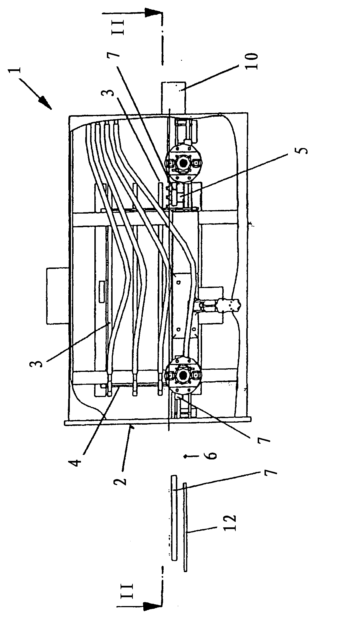
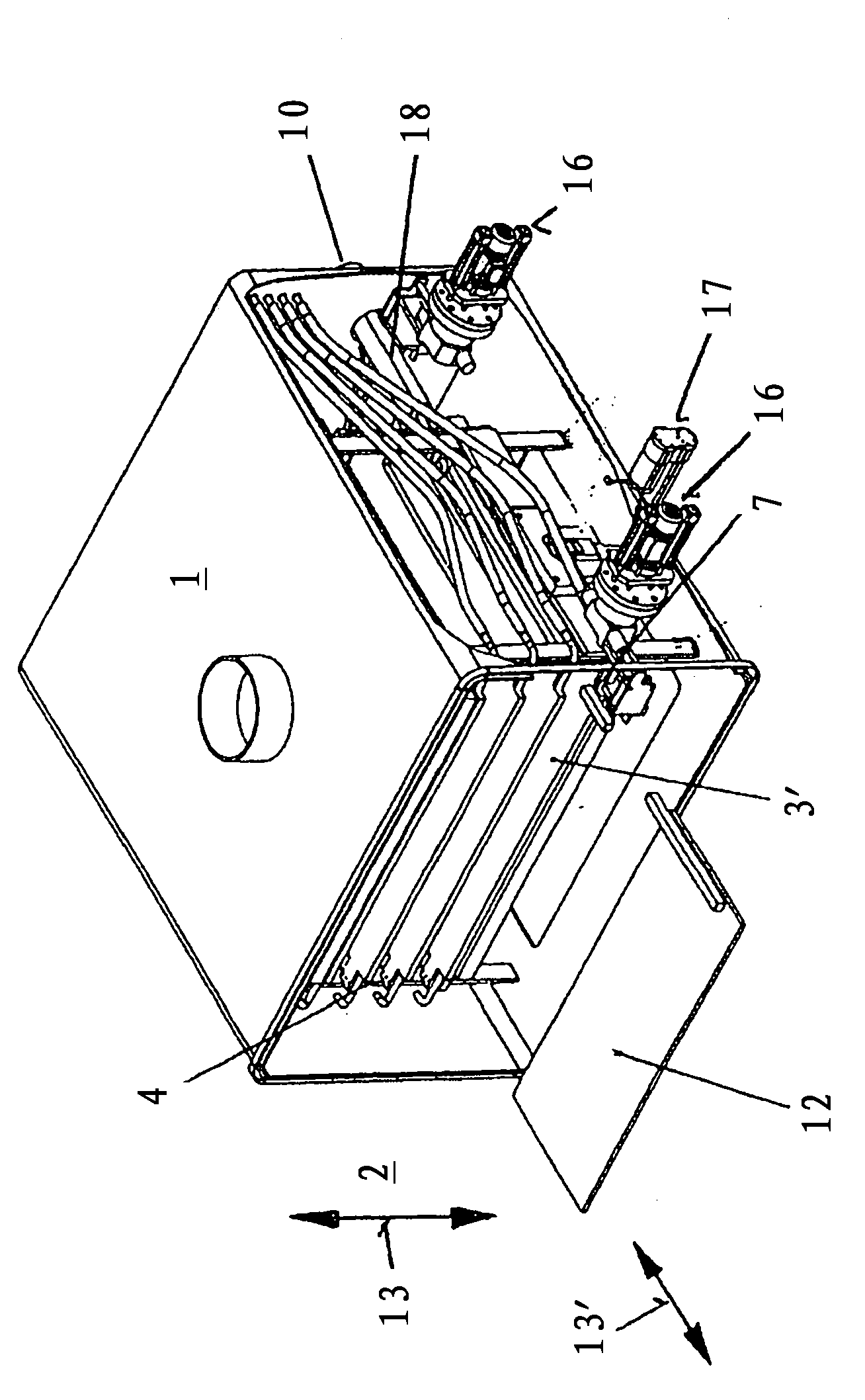
[0030] figure 1 The drying chamber 1 of the freeze-drying plant is shown in section, in whose front side 2 there is a not shown closeable opening for loading and unloading drying containers 5 . The drying chamber 1 is connected to the condenser chamber in a known manner, but will not be described in detail here.

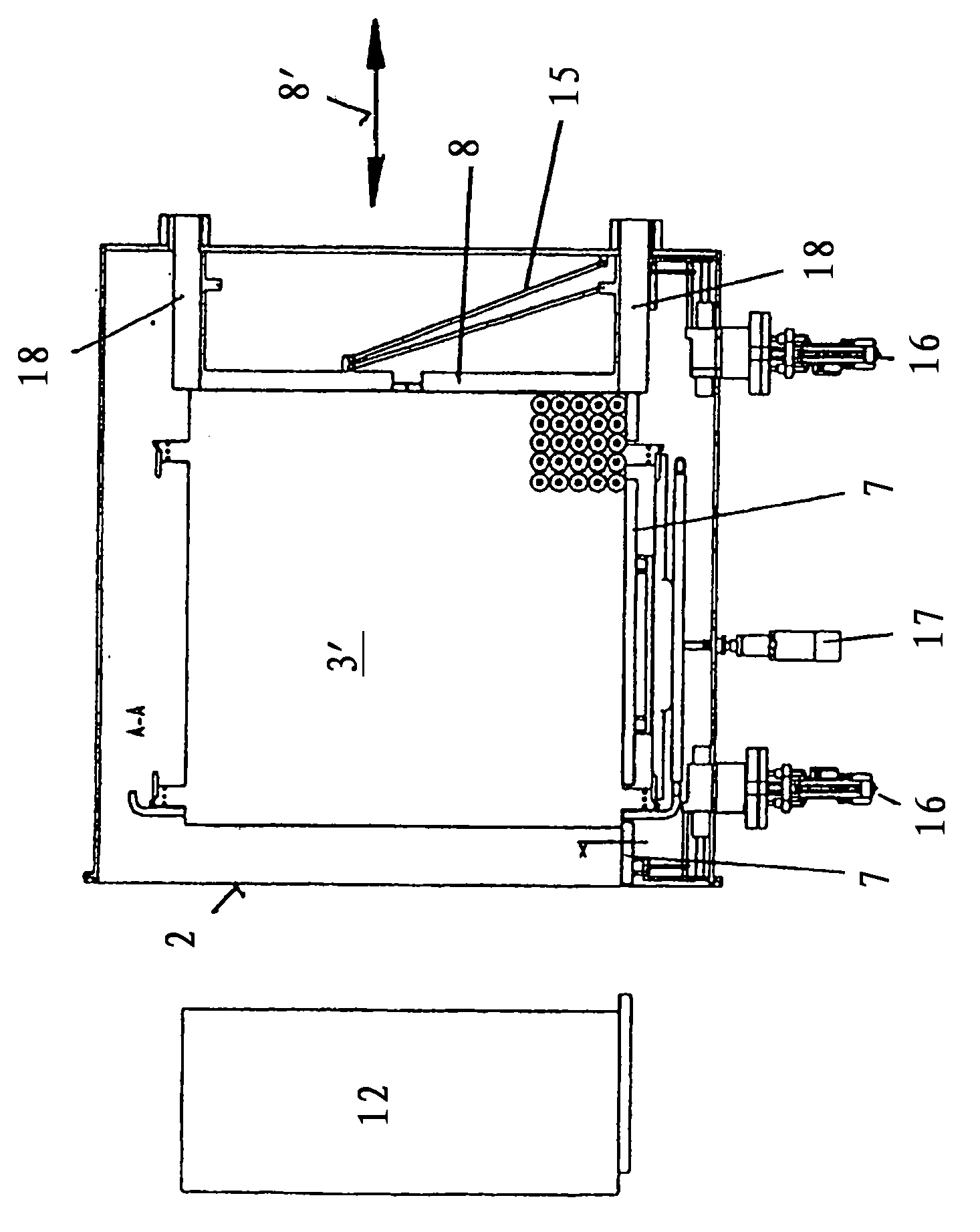
[0031] Located in the drying chamber 1 is an assembly consisting of a rest surface, which is held vertically displaceably in a known manner in a support 4 . The support surface 3 is used for vertically placing drying containers 5 , each containing a drying substance, which can be removed from the drying chamber 1 after the drying process has been completed. The height position of the placement surface 3 ′, which corresponds to the unloading position of this placement surface, is indicated with reference numeral 6 . It is important that the vertical adjustability of all placement surfaces 3 of the support 4 is arranged in such a way that each placement surface 3 can...


PUM


Abstract

The invention relates to a device essentially for loading and unloading the floor area (3') of the drying chamber (2) of a freeze-drying installation, said floor area being located at a defined height position of the unloading position, which is characterised by a carriage (8) that is arranged slightly above said floor area, extends transversely to a movement direction (8') during loading or unloading and parallel to the floor area and forms a movable guiding edge for the drying vessels (5), and by guides (7) that are arranged on both sides of the floor area (3'), extend parallel to said movement direction and form fixed guiding edges for the drying vessels (5). The carriage (8) is driven by two linear motors, the respective secondary parts (18) of which are rigidly connected to the two ends of the carriage (8) and on which the guides (7) simultaneously receiving the primary parts are mounted. All components of the device thus defined are located inside the drying chamber (1), resulting in a mechanically extremely simple, low-wear construction. The structural design of such a device permits the implementation of lateral guides (7) independent of the floor area within the drying chamber (2) and is suitable for a retrofitting by progressive stages of existing freeze-drying installations with a view to using a plurality of carriages, rendering the guides (7) displaceable laterally, i.e. transversely to the movement direction (8'), etc.. Because the essential components of said device can be constructed in a hermetically sealed manner and can therefore easily be sterilised, from the point of view of hygiene the device can be managed safely.

Description

technical field [0001] The invention relates to a loading and / or unloading device for a freeze-drying plant with the features of the preamble of corresponding claim 1 . Background technique [0002] Such a device is known from German patent application 102009049142.2-16 of 12.10.2009 by the applicant. [0003] The freeze-drying method is used for heat-sensitive goods, such as pharmaceutical and biochemical products, food, etc., wherein the dry goods are first frozen, crystallized ice is sublimated from the goods under vacuum and falls out again as ice on the condenser. For this purpose, the pressure, temperature and other parameters of the drying process are controlled and monitored according to a product-specific sublimation pressure curve in order to obtain a reproducible dried product. The energy required for sublimation is generally supplied by heating. [0004] Freeze-drying plants are in many cases designed for discontinuous operation and essentially comprise a dryin...

Claims


Application Information

Patent Timeline
Patent Type & Authority Applications(China)
IPC IPC(8): F26B5/06F26B25/00
CPCF26B5/06F26B25/001F26B25/003
Inventor M·克里斯特
Owner MARTIN CHRIST GEFRIERTROCKNUNGSANLAGEN
Why Eureka
Try Eureka