Sludge drying device and sludge treatment system

A sludge drying and sludge technology, applied in the direction of dehydration/drying/concentrated sludge treatment, etc., can solve problems such as hot flue gas pollution, and achieve the effects of reducing pollution, high drying efficiency, and simple structure

Active Publication Date: 2013-01-16
湖南省益能环保科技有限公司
View PDF3 Cites 8 Cited by
  • Summary
  • Abstract
  • Description
  • Claims
  • Application Information

AI Technical Summary

Problems solved by technology

During the drying process, due to the direct contact between the sludge and the hot flue gas, the toxic and harmful gases in the sludge are directly discharged into the hot flue gas, thereby causing serious pollution to the hot flue gas

Method used


Image

  • Sludge drying device and sludge treatment system
  • Sludge drying device and sludge treatment system
  • Sludge drying device and sludge treatment system

Examples


Embodiment Construction

[0037] In the following, the present invention will be further described in conjunction with the accompanying drawings and specific embodiments, so as to understand the technical ideas claimed in the present invention more clearly.

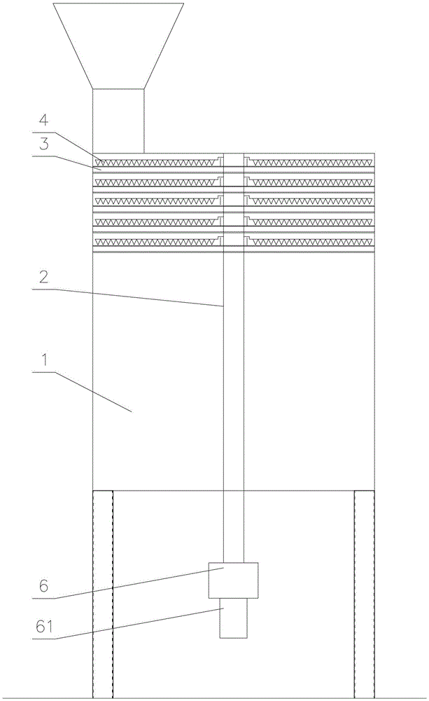
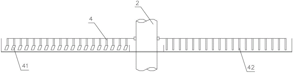
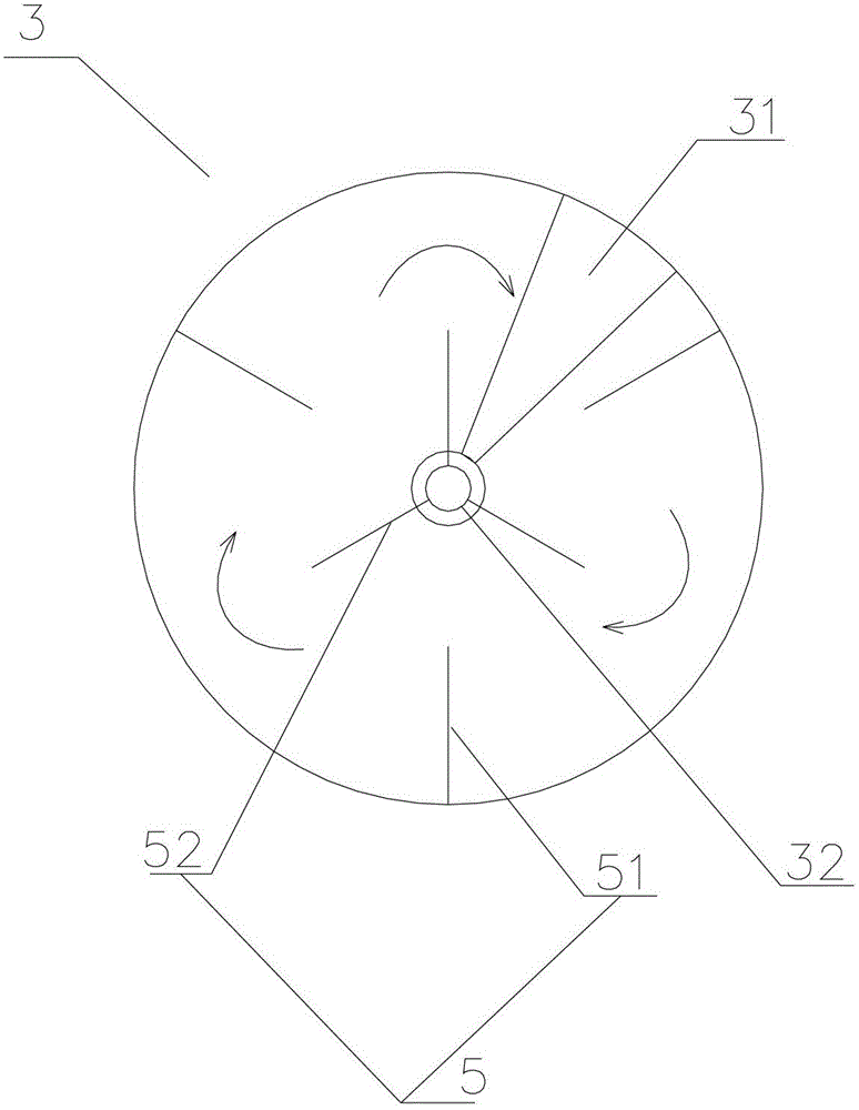
[0038] Such as figure 1 As shown, the sludge drying device of the present invention includes a drying chamber 1, a heat transfer wind box 3, an agitator 4, a rotating shaft 2, and a driving device for driving the rotating shaft 2 to rotate. The drying chamber 1 is provided with a feeding port and a feeding port. During operation, sludge enters the chamber from the feeding port of the drying chamber 1 and is discharged from the feeding port. Specifically, the feeding port and the feeding port are respectively arranged at the upper and lower ends of the drying chamber 1, and the sludge drying device further includes a sludge crushing device arranged on the feeding port. By adopting the design of the sludge crushing device, it is convenient to brea...


PUM


Abstract

The invention discloses a sludge drying device and a sludge treatment system. The sludge drying device comprises a drying chamber, a rotating shaft, a driving device, a heat transfer air box and a stirrer, wherein the heat transfer air box is hollow shell-shaped; a smoke chamber, an air inlet and an air outlet which are communicated with the smoke chamber are arranged in the heat transfer air box; the upper surface of the heat transfer air box is used for receiving and drying sludge; the heat transfer air box is provided with a discharge hole which extends from the upper surface to the lower surface of the heat transfer air box; a discharge partition plate which extends from the upper surface to the lower surface of the heat transfer air box is also arranged in the heat transfer air box; the smoke chamber of the heat transfer air box is isolated from the discharge hole by the discharge partition plate; and the stirrer is provided with a scraper. In a drying process, hot smoke enters the smoke chamber of the heat transfer air box through the air inlet, the heat of the hot smoke is supplied to the heat transfer air box, and the sludge is heated on the upper surface of the heat transfer air box to evaporate moisture so as to fulfill the aim of drying; and thus, the sludge can be prevented from being directly contacted with the hot smoke, and the pollution of the hot smoke is reduced.

Description

[0001] technical field [0002] The invention relates to the field of sludge drying, in particular to a sludge drying device and a sludge treatment system. Background technique [0003] Existing sludge drying devices generally include a drying chamber, a roller arranged laterally in the drying chamber, and a scraper arranged on the roller. When working, the hot flue gas is directly introduced into the drying chamber from the air inlet at the lower end of the drying chamber, and the sludge in the drying chamber can be broken up and fully mixed with the hot flue gas through the stirring of the scraper, so as to achieve The purpose of drying evenly. During the drying process, due to the direct contact between the sludge and the hot flue gas, the toxic and harmful gases in the sludge are directly discharged into the hot flue gas, thereby causing serious pollution to the hot flue gas. Contents of the invention [0004] Aiming at the deficiencies of the prior art, one of the p...

Claims


Application Information

Patent Timeline
Patent Type & Authority Applications(China)
IPC IPC(8): C02F11/12
Inventor 冯本剑
Owner 湖南省益能环保科技有限公司
Why Eureka
Try Eureka