Super high-speed quenching device for steel tube

A cooling device, ultra-fast technology, applied in the direction of quenching device, furnace, heat treatment equipment, etc., can solve the problems that the cooling device does not have ultra-fast cooling, can not achieve ultra-fast cooling effect, and the cooling uniformity is not uniform, etc., to achieve structural Simple, convenient installation and disassembly, and the effect of inhibiting bending deformation

Active Publication Date: 2013-01-16
沈阳科安捷材料技术有限公司
View PDF6 Cites 7 Cited by
  • Summary
  • Abstract
  • Description
  • Claims
  • Application Information

AI Technical Summary

Problems solved by technology

However, due to the design form of its nozzle, the cooling device does not have the characteristics of ultra-fast cooling and cannot achieve the effect of ultra-rapid cooling; and this nozzle form will cause the sprayed water to be used only at the axis of the vertical circular inner cavity The steel pipe is partially cooled, and after use, it will flow away from the water leak under the device, which has not been fully utilized; in addition, the structure of the nozzle is different for steel pipes with different diameters, and the coverage area of ​​water sprayed on the surface of the steel pipe is different. , under the same nozzle structure conditions, the water coverage area on the surface of the steel pipe with a large diameter is small, and the water coverage area on the surface of the steel pipe with a small diameter is large, which will cause uneven cooling uniformity

Method used


Image

  • Super high-speed quenching device for steel tube
  • Super high-speed quenching device for steel tube
  • Super high-speed quenching device for steel tube

Examples


Embodiment Construction

[0028] The present invention will be further described below in conjunction with the accompanying drawings and specific embodiments.

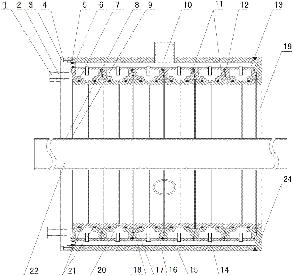
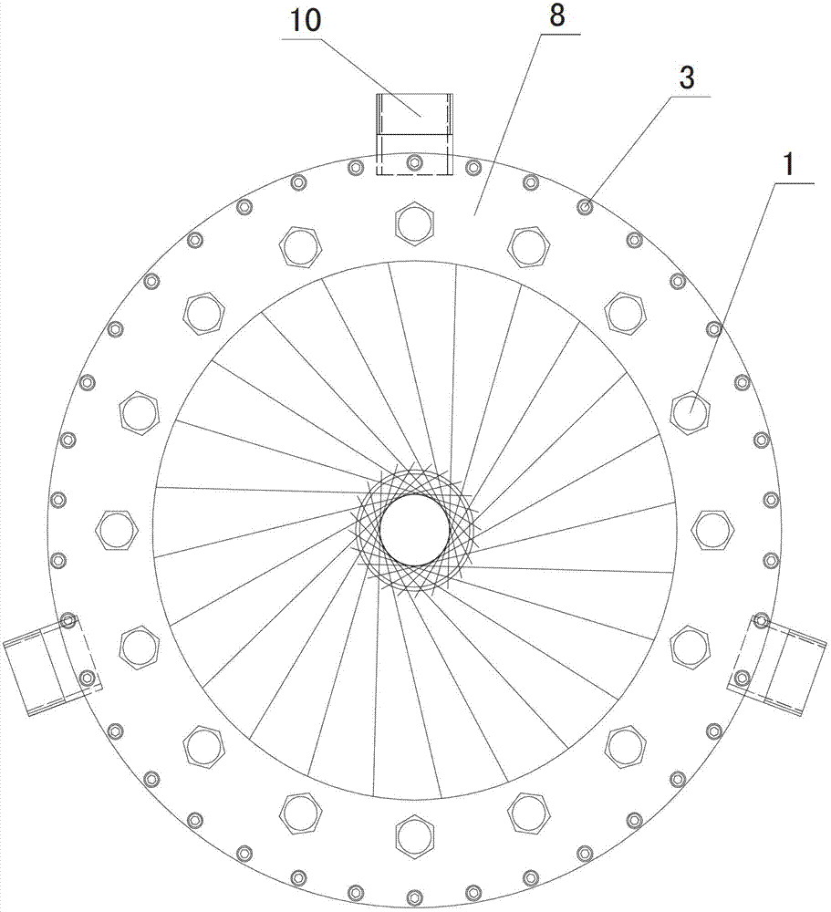
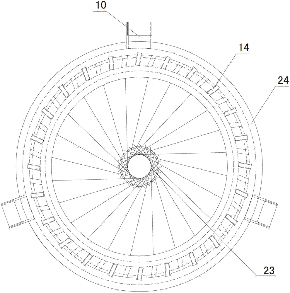
[0029] Such as Figure 1~3 As shown, a steel pipe ultra-rapid quenching cooling device is a cylindrical structure, including a casing 15 with a water inlet 10, and a number of oblique nozzle units 11 are arranged in the casing 15. The present embodiment adopts 6 slanted nozzle units 11, that is, the water flow will be sprayed from the six slanted nozzles 20, and the sprayed water flow has the same forward or backward trend as the cooling steel pipe 22 running direction, along the cooling steel pipe 22. The wall spiral jets forward or backward. The first pressing plate 8 and the second pressing plate 9 are closely pressed together with the six oblique nozzle units 11 side by side through several pressing bolts 1 and nuts 2, and the first pressing plate is pressed together through several bolts 3 and washers 4. The tight plate 8 is fixed togeth...


PUM


Abstract

The invention discloses a super high-speed quenching device for a steel tube and relates to a cooling device. The quenching device comprises a shell with water inlets; a plurality of inclined seam nozzle units are arranged in the shell and are pressed against each other in parallel; gaps are reserved between the shell and the inclined seam nozzle units and are cooling water layers; each inclined seam nozzle unit has an annular structure, and sequentially consists of a water guide plate, a flow stabilization layer wall plate and a nozzle adjustment sleeve plate from exterior to interior; a plurality of water guide columns are uniformly distributed on the circumference of each water guide plate; the extension lines of the water spraying directions of all the water guide columns are intersected to form an inscribed circle, and the diameter of the inscribed circle is less than or equal to that of the steel tube to be cooled; the water guide columns of the adjacent inclined seam nozzle units are staggered; an inner cavity which is formed by the flow stabilization layer wall plates has a shape of a funnel with a wide exterior and a narrow interior; each nozzle adjustment sleeve plate is annular; gaps between the nozzle adjustment sleeves plates are inclined seam nozzles; the inclined seam nozzles are inclined seams of which the width is gradually reduced from exterior to interior.

Description

technical field [0001] The invention relates to a cooling device, in particular to a device for ultra-rapid quenching and cooling of steel pipes. Background technique [0002] The boiling heat transfer phenomenon of steel pipe water cooling is mainly in two states. One is that the steel pipe is in direct contact with water to realize heat exchange. This boiling heat transfer phenomenon has a strong cooling capacity and is nucleate boiling. The other is that a steam film is formed between the steel pipe and the cooling water, and heat exchange is performed through the steam film, which is film boiling. When the steel pipe is accelerated to cool, at the beginning of cooling, the surface temperature is high, and the film boiling state is dominant. However, if the surface temperature gradually decreases, the steam film becomes unstable, and at this time, the local cooling water begins to contact the steel pipe, gradually turning into nucleate boiling. Between film boiling and ...

Claims


Application Information

Patent Timeline
Patent Type & Authority Applications(China)
IPC IPC(8): C21D9/08C21D1/667
Inventor 骆宗安王国栋冯莹莹吴庆林
Owner 沈阳科安捷材料技术有限公司
Why Eureka
Try Eureka