Weft knitting mechanism

A technology of weft and warp, applied in the field of weaving mechanism, can solve the problems that the service life does not reach the expected effect, damage the physical and mental health of the workers, and can not last for a long time, and achieves the improvement of labor productivity, simple structure and improved weaving quality. Effect

Inactive Publication Date: 2013-01-16
周传对
View PDF10 Cites 4 Cited by
  • Summary
  • Abstract
  • Description
  • Claims
  • Application Information

AI Technical Summary

Problems solved by technology

In this way, the effect is more obvious at the beginning. The power of the motor driving the shuttle boat has been reduced from the original 6 or 7 kilowatts to 3 kilowatts. The noise and the wear of the shuttle bottom plate have been improved to a certain extent. However, because the roller track is also responsible for the warp separation function , so that the diameter of the rollers on the roller track is limited. Due to the small diameter of the rollers, rolling bearings cannot be used. Although there is rolling friction between the shuttle bottom plate and the rollers, there is still friction between the rollers and the mandrel supporting the rollers. Sliding friction, the sliding friction between the smaller-diameter roller and the smaller-diameter mandrel does not last long, the gap between the roller and the mandrel becomes larger, and the mandrel deforms, causing the noise to become louder again, and the rolling The column and mandrel need to be replaced frequently, and the phenomenon of broken wires has not improved
[0006] In order to overcome the problem of easy wear and tear of rollers and mandrels, the fourth-generation weft weaving mechanism replaced the shuttle bottom pla

Method used


Image

  • Weft knitting mechanism
  • Weft knitting mechanism
  • Weft knitting mechanism

Examples


Embodiment

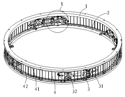
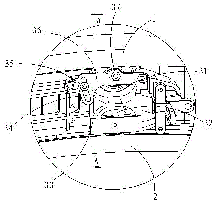
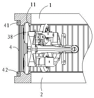
[0022] Example: A weft knitting mechanism, such as figure 1 , figure 2 , image 3 As shown, the upper door ring 1 and the lower door ring 2 are included. The outer edges of the upper door ring 1 and the lower door ring 2 are respectively provided with steps formed by removing materials. The upper door ring 1 is fastened with an upper fixing strip 41 and the lower door A lower fixing strip 42 is firmly connected in the step of the ring 2, and the upper fixing strip 41 and the lower fixing strip 42 are connected by a plurality of dividing strips 4 made of iron wire, and the plurality of dividing strips 4 are arranged in parallel and equidistant, and the upper door ring 1. The opposite sides of the lower door ring 2 are respectively provided with an annular circular arc concave surface 11, the arc concave surface 11 is offset to the inner circumferential surface of the upper door ring 1 and the lower door ring 2, and the circular arc concave surface 11 is respectively opposite to ...


PUM


Abstract

The invention discloses a weft knitting mechanism which comprises an upper door ring and a lower door ring, wherein a shuttle boat is arranged between the upper door ring and the lower door ring; the shuttle boat is provided with an upper shuttle wheel and a lower shuttle wheel; the outer edges of the upper door ring and the lower door ring are connected with each other by a warp separating device; two guide devices are respectively arranged between the upper door ring and the shuttle boat as well as between the lower door ring and the shuttle boat; the upper shuttle wheel arranged on the shuttle boat is connected with the lower side of the upper door ring by the guide device; the lower shuttle wheel arranged on the shuttle boat is connected with the upper side of the lower door ring by the guide device; and at least one of the upper shuttle wheel and the lower shuttle wheel is connected with the shuttle boat by a regulating mechanism. The weft knitting mechanism has the beneficial effects of being simple in structure, reasonable in design, convenient to manufacture, lower in driving resistance, low in noise and abrasion and free from yarn break, thus improving the knitting quality of products.

Description

Technical field [0001] The invention relates to a knitting mechanism, in particular to a weft knitting mechanism that can be used in a mesh machine or a circular loom. Background technique [0002] Mesh machines and circular looms have a history of nearly 30 years since their birth. With the development of technology and the unremitting efforts of scientific and technical personnel, the weft knitting mechanism is eliminating noise, reducing energy consumption, extending service life, saving costs, and convenient operation. Glorious technological progress has been made in terms of sex. [0003] The first generation of weft knitting mechanism sets the two opposite sides of the ring-shaped upper and lower door rings as inclined surfaces. The distance between the outer sides of the circumference of the two inclined surfaces is smaller than the distance between the inner sides, relying on the inclined surface to support the shuttle boat The component force generated by the force acts a...

Claims


Application Information

Patent Timeline
IPC IPC(8): D03D37/00D04C3/00
Inventor 周传对
Owner 周传对
Why Eureka
Try Eureka