Engine speed control system and engineering machine

A technology of engine speed and control system, applied in the direction of engine control, machine/engine, mechanical equipment, etc., can solve the problems of low control accuracy and easy signal interference, so as to improve control accuracy, reduce physical distance, and avoid energy waste Effect

Active Publication Date: 2015-04-22
SANY HEAVY IND CO LTD (CN)
View PDF5 Cites 0 Cited by
  • Summary
  • Abstract
  • Description
  • Claims
  • Application Information

AI Technical Summary

Problems solved by technology

[0005] In view of this, the present invention aims to propose an engine speed control system and construction machinery to solve the problems in the prior art that the signal is easily disturbed and the control accuracy is not high when the engine speed is controlled by the accelerator pedal.

Method used


Image

  • Engine speed control system and engineering machine
  • Engine speed control system and engineering machine
  • Engine speed control system and engineering machine

Examples


Embodiment Construction

[0024] It should be pointed out that the description and sequence of specific structures in this section are only descriptions of specific embodiments, and should not be considered as limiting the protection scope of the present invention. In addition, the embodiments in this section and the features in the embodiments can be combined with each other under the condition of no conflict.

[0025] Please refer to figure 1 , the embodiments of the present invention will be described in detail below with reference to the accompanying drawings.

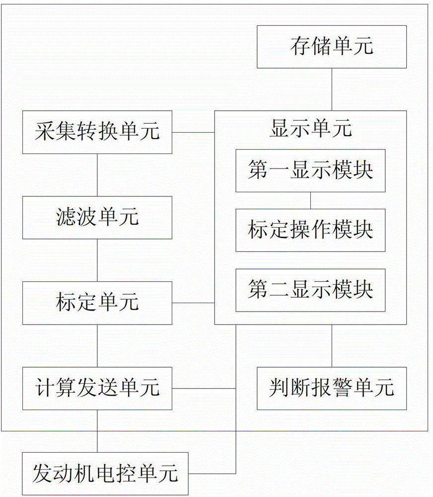
[0026] As shown in the figure, the engine speed control system of this embodiment at least includes an acquisition unit, a calibration unit and a calculation and sending unit. The acquisition conversion unit is used to acquire the state signal (generally a voltage signal) of the accelerator pedal and convert it into a digital signal, wherein the state signal of the accelerator pedal corresponds to the first digital signal when the accelera...


PUM


Abstract

The invention discloses an engine speed control system and an engineering machine. The engine speed control system comprises an acquisition conversion unit, a calibration unit and a calculation transmitting unit. The acquisition conversion unit is used for acquiring signals about statuses of an accelerator pedal and converting the signals into digital signals, the signal about the status that the accelerator is not stepped corresponds to a first digital signal, and the signal about the status that the accelerator pedal is full stepped corresponds to a second digital signal. The calibration unit is used for subjecting the digital signals obtained by the acquisition conversion unit to data acquisition with engine speed, the first digital signal corresponds to idle speed, and the second digital signal corresponds to maximum adjustable speed. The calculation transmitting unit is used for calculating the corresponding engine control speed according to the current digital signal obtained by the acquisition conversion unit and transmitting the engine control speed to an engine electro-control unit. By the use of the engine speed control system, speed fluctuation due to the fact that analog signals are interfered can be avoided, precision in controlling engine speed can be improved and cost in check and maintenance of the accelerator pedal can be reduced.

Description

technical field [0001] The invention relates to the field of construction machinery, in particular to an engine speed control system and construction machinery. Background technique [0002] At present, the accelerator control of the crane on the car is generally passed an analog signal to the engine of the off car. The analog signal is usually a voltage signal, ranging from 0 to 5V. The operator will make the accelerator pedal The potentiometer sends a corresponding voltage signal to the down-car engine, thereby controlling the down-car engine to run between idle speed and maximum speed. [0003] However, since the accelerator pedal of the vehicle is installed in the control room of the vehicle, and the control room needs to be rotated 360 degrees according to the requirements of the hoisting, the signal line of the potentiometer of the accelerator pedal needs to be transmitted through the conductive ring installed on the rotation center. To get off the car, in this proces...

Claims


Application Information

Patent Timeline
Patent Type & Authority Patents(China)
IPC IPC(8): F02D11/10F02D29/00
Inventor 李丰罗艳霞彭光林
Owner SANY HEAVY IND CO LTD (CN)
Why Eureka
Try Eureka