Self-aligning thrust bearing for submerged pump

A thrust bearing and self-aligning technology, applied in the mechanical field, can solve the problems that the center of gravity and the axis cannot overlap, the service life of a pump is shortened, and the wear of the thrust bearing increases.

Active Publication Date: 2013-01-16
JINZHOU WATER PUMP FACTORY
View PDF5 Cites 6 Cited by
  • Summary
  • Abstract
  • Description
  • Claims
  • Application Information

AI Technical Summary

Problems solved by technology

Due to the uncertainty of manufacturing errors and assembly errors, the center of gravity and the axis cannot overlap, and the thrust bearing cannot fully contact when rotating.
If the situation is serious, the contact area is too small, the pressure is high, and the temperature of the contact surface is too high, which will rapidly increase the wear of the thrust bearing and greatly shorten the service life of a pump.

Method used


Image

  • Self-aligning thrust bearing for submerged pump
  • Self-aligning thrust bearing for submerged pump
  • Self-aligning thrust bearing for submerged pump

Examples


Embodiment 1

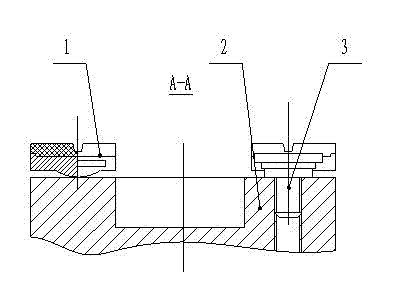
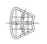
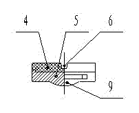
[0031] The present invention proposes a self-aligning type thrust bearing for a submersible pump, such as figure 1 , figure 2 , Figure 5 , Image 6 , Figure 7 As shown, it includes a disk-shaped base 2 and at least two thrust bearing blocks 1 evenly distributed on the circumference of the base. The thrust bearing block 1 is composed of a base 5 made of metal and a friction plate 4 made of polymer material. At least one concave water channel 6 is provided on the surface of the friction plate 4, a protrusion 6 is provided in the middle of the bottom 5 of the base, the protrusion 6 is arranged in contact with the base 2, and the thrust bearing block has a locking mechanism, So that the thrust bearing block 1 can be fixed on the base 2 .

[0032] The clamping mechanism is a boss 7-2 respectively arranged on both sides of the thrust bearing block, and the two ends of the boss 7-2 are provided with stoppers. When the thrust bearing block 1 is installed on the base 2 , the he...

Embodiment 2

[0034] like image 3 , Figure 4 , Figure 8 , Figure 9 As shown, as another form of the snap-in mechanism, the snap-in mechanism is a groove 7-1 respectively provided on both sides of the thrust bearing block 1, when the thrust bearing block 1 is installed on the base 2 , the heads of the fixing bolts 3 are accommodated in the grooves 7-1 of the two adjacent thrust bearing blocks 1, the circumference of the disc-shaped base is provided with mounting holes, and the fastening bolts are fastened on the mounting hole to secure the thrust bearing block.

Embodiment 3

[0036] like Figure 10 , Figure 11 As shown, as another form of the clamping mechanism, the clamping mechanism is the installation through hole 8 respectively provided on both sides of the protrusion 9. When the thrust bearing block is installed on the base, the fixing bolt Fastened in the installation through hole 8, the circumference of the disc-shaped base is provided with installation holes, and the fastening bolts are fastened in the installation holes, thereby fixing the thrust bearing block on the base.

[0037] like Figure 12 , Figure 13 As shown, the head of the fixing bolt is composed of two cylinders with different diameters superimposed, wherein the cylinder with a larger diameter is located at the top of the head, and the top of the head of the fixing bolt is provided with an inner hexagon. During installation, the end face of the smaller cylinder contacts with the base 2 to generate frictional force, which prevents the screw from rotating, and plays a guidi...


PUM


Abstract

The invention discloses a self-aligning thrust bearing for a submerged pump, which comprises a disc-shaped pedestal and at least two thrust bearing blocks uniformly distributed on the circumference of the pedestal; the thrust bearing bocks are composed of bases which are made of metal materials and friction sheets made of high molecular materials; at least one concave waterway is arranged on the surfaces of the friction sheets; a boss is arranged in the middles of the bottom surfaces of the bases; the boss is contacted with the pedestal; and the thrust bearing blocks are provided with clamping mechanisms to fix the thrust bearing blocks on the pedestal. The self-aligning thrust bearing aims at turning a fixing plane type thrust bearing into a self-aligning thrust bearing by changing the structure form of the original design; owing to the design of the boss at the bottom of the thrust bearing, the thrust bearing blocks are inclined to modify the matching precision, so as to remarkably increases the contact area of the thrust bearing blocks and reduce the pressure; the multiple movable friction blocks are synchronously abraded, thereby greatly prolonging the service life of the submerged electric pump. The processing part is simple and easy to realize and is comparatively low in cost; and with application of the self-aligning thrust bearing, the service life of the product is prolonged.

Description

technical field [0001] The invention belongs to the field of machinery and relates to a self-aligning thrust bearing for a submersible pump. [0002] Background technique [0003] The submersible pump is a mechanical device that rotates at high speed. The working type is usually vertical, and the weight of the motor and pump is all carried by the thrust bearing. Due to the uncertainty of manufacturing errors and assembly errors, the center of gravity and the axis cannot overlap, and the thrust bearing cannot fully contact when rotating. If the situation is serious, the contact area is too small, the pressure is high, and the temperature of the contact surface is too high, which will increase the wear of the thrust bearing rapidly and greatly shorten the service life of a pump. [0004] Contents of the invention [0005] In order to overcome the defects and deficiencies of the prior art, the present invention proposes a self-aligning thrust bearing that can prolong the ...

Claims


Application Information

Patent Timeline
Patent Type & Authority Applications(China)
IPC IPC(8): F04D29/046
Inventor 路志强
Owner JINZHOU WATER PUMP FACTORY
Why Eureka
Try Eureka