Light source mechanism capable of moving along spherical track

A technology of spherical motion and light source, applied in the field of mechanical structure, can solve the problems of inability to irradiate equipment in real time and guarantee equipment, and achieve the effect of consistent illuminance and flexible positioning

Inactive Publication Date: 2013-01-16
CHANGCHUN INST OF OPTICS FINE MECHANICS & PHYSICS CHINESE ACAD OF SCI
View PDF6 Cites 4 Cited by
  • Summary
  • Abstract
  • Description
  • Claims
  • Application Information

AI Technical Summary

Problems solved by technology

The movement trajectory of the local device receiving the light of the equipment is often a spherical surface with the intersection of the axes as the center of the sphere. The existing light sou

Method used


Image

  • Light source mechanism capable of moving along spherical track
  • Light source mechanism capable of moving along spherical track

Examples


Embodiment 1

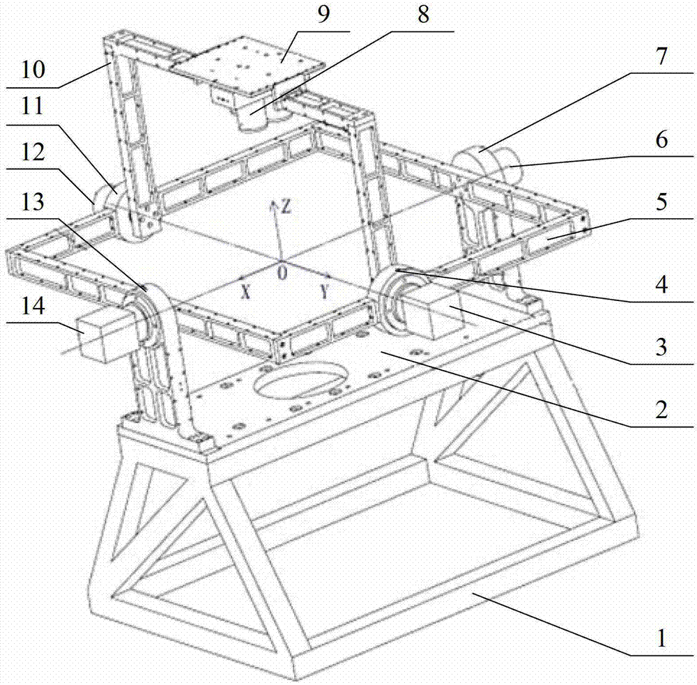
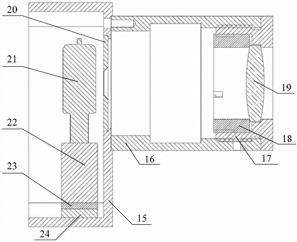
[0020] See attached figure 1 , 2 The light source mechanism of the present invention includes a two-dimensional motion mechanism and a light source assembly 8 capable of emitting parallel light. Frame driven end shaft system 7, outer frame motor-reducer 14, outer frame encoder 6, inner frame 10, inner frame driving end shaft system 4, inner frame driven end shaft system 11, inner frame motor-reducer 3 , an inner frame encoder 12, a light source mounting plate 9; the stage 2 and the bottom bracket 1 are connected by bolts, the outer frame driving end shaft system 13 and the outer frame driven end shaft system 7 are fixed on the object stage 2, The outer frame motor-reducer 14 is fixed on the outer frame driving end shafting 13, the outer frame encoder 6 is fixed on the outer frame driven end shafting 7, and the inner frame 10 passes through the inner frame driving end shafting 4 and the inner frame driven end The shaft system 11 is connected to the outer frame 5, and the ligh...

Embodiment 2

[0025] The outer frame 5 of the two-dimensional motion mechanism is a 630mm×702mm square frame, and the inner frame 10 is a half frame of 650mm×340mm. The inner frame 10 and the outer frame 5 are larger in size, and because the load is smaller, in order to save manufacturing costs, the inner frame 10 and the outer frame 5 are spliced ​​by straight aluminum alloy plates. The four shaft systems of the mechanism all use paired angular contact ball bearings with an outer diameter of 42mm, and the shaft material is 40Cr. The motor-reducer assembly selects a 42-type motor, which is matched with a planetary reducer to achieve a reduction ratio of 100 times and provide a maximum torque of 50N.m. The encoder selects a 14-bit absolute hollow shaft encoder to ensure the accuracy of rotation measurement. During installation, the main and driven end shafting of the outer frame and the main and driven end shafting of the inner frame are assembled first, and then the main and driven end sha...


PUM


Abstract

The invention provides a light source mechanism capable of moving along a spherical track, belongs to the field of mechanical structures, and particularly relates to a uniform-illumination parallel light source device capable of directly emitting light rays from various angles. The light source mechanism can move along the spherical track through a two-dimensional moving mechanism, uniform parallel light sources capable of directly emitting light rays from various angles can be formed by combining light sources, and spatial positions of the light sources can be accurately controlled and positioned. The light source mechanism comprises the two-dimensional moving mechanism and a light source assembly capable of emitting parallel light rays, wherein an inner frame and an outer frame in the two-dimensional moving mechanism rotate around respective axes; the outer frame simultaneously drives the inner frame to rotate; the light sources circularly move in the X-axis direction and the Y-axis direction respectively, so that a spherical motion track is formed; light rays emitted from the light sources directly face a sphere center within a range of the motion track all the time, the distances from the light rays to the sphere center are equal, and consistency of illumination is kept. The position of a spherical center point of the spherical track of the light sources is changed by changing the positions of the light sources on a light source mounting plate.

Description

technical field [0001] The invention relates to the field of mechanical structures, in particular to a light source mechanism capable of realizing a spherical motion trajectory, in particular to a device for realizing parallel light sources with uniform and equal illumination directed directly from various angles. Background technique [0002] In scientific research experiments, various experimental light sources are widely used; some equipment such as radiometers, theodolites and other optical signal tracking equipment move in space around one axis or two axes, requiring the equipment to rotate to any angle in space Can receive parallel light with equal illuminance. The movement trajectory of the local device receiving the light of the equipment is often a spherical surface with the intersection of the axes as the center of the sphere. The existing light source mechanism is generally fixed and installed, which cannot irradiate the equipment in real time, and cannot ensure t...

Claims


Application Information

Patent Timeline
IPC IPC(8): F21S2/00F21V14/02
Inventor 王玉鹏方伟姜明王凯叶新
Owner CHANGCHUN INST OF OPTICS FINE MECHANICS & PHYSICS CHINESE ACAD OF SCI
Why Eureka
Try Eureka