
Sound field analysis method based on image recognition positioning and acoustic sensor array measurement

An acoustic sensor and image recognition technology, which is applied to the measurement of ultrasonic/sonic/infrasonic waves, measuring devices, instruments, etc., can solve the problems of low work efficiency, high work intensity, and high complexity of acoustic sensor positioning, and achieve high work efficiency and low labor costs. The effect of low intensity, reducing test difficulty and complexity

Inactive Publication Date: 2013-01-16
SHANGHAI JIAO TONG UNIV
View PDF4 Cites 24 Cited by
  • Summary
  • Abstract
  • Description
  • Claims
  • Application Information

AI Technical Summary

Problems solved by technology

[0007] The purpose of the present invention is to provide a sound field analysis system based on image recognition and positioning and acoustic sensor array measurement to solve the problems of high acoustic sensor positioning complexity, low work efficiency and high work intensity in the existing near-field acoustic holographic noise source positioning method technical problem
[0008] Another object of the present invention is to provide a sound field analysis method based on image recognition and positioning and acoustic sensor array measurement to solve the existing near-field acoustic holographic noise source positioning method with high complexity of acoustic sensor positioning, low work efficiency and work intensity big technical problem

Method used


Image

  • Sound field analysis method based on image recognition positioning and acoustic sensor array measurement
  • Sound field analysis method based on image recognition positioning and acoustic sensor array measurement

Examples


Embodiment 1

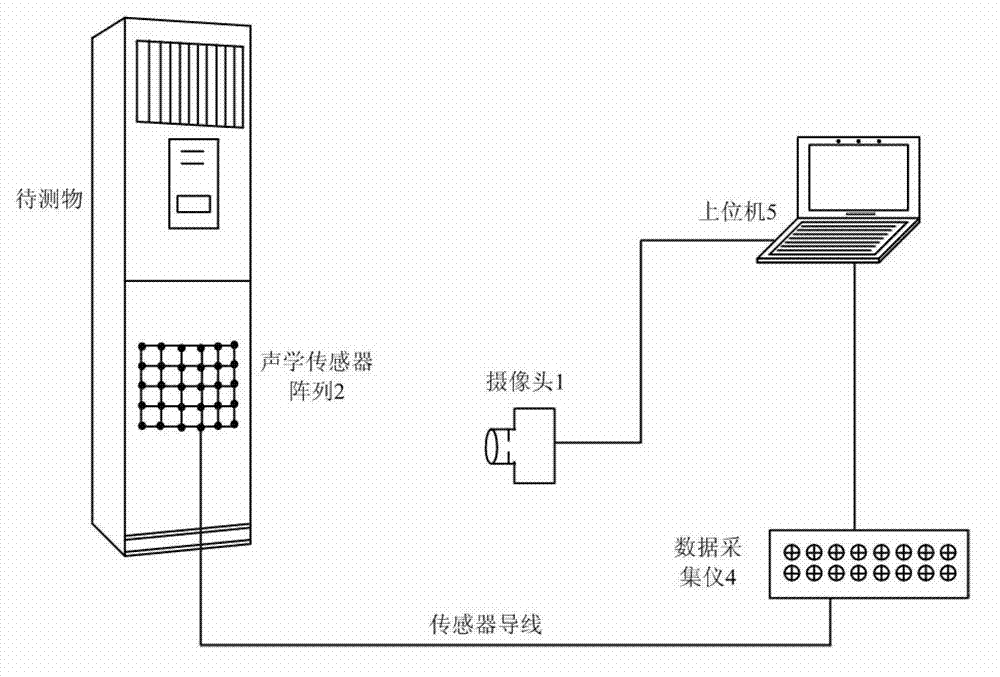
[0045] Please also refer to figure 1 and figure 2 , a sound field analysis method based on image recognition positioning and acoustic sensor array measurement, comprising the following steps:

[0046] 1. Take the vertical air conditioner indoor unit as the sound source to be tested, detect the sound field distribution in a certain area in front of it, adjust the position and focal length of camera 1 so that the area captured includes the area to be tested, and connect the signal of camera 1 to interface 5 of the host computer , take an image and save it in the host computer 5 as a background image.

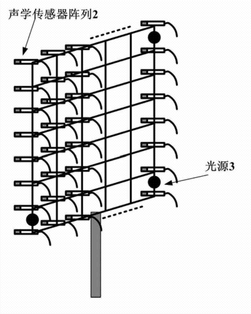
[0047] 2. Fix the light-emitting diodes as the light source 3 to the three corners of the acoustic sensor array 2, supply power with batteries to make them emit light, and connect the signal wires of the array to the data acquisition instrument 4. Through light filtering, the color of the light source is highlighted in the image captured by the camera 1, and other colors in the...


PUM


Abstract

The invention discloses a sound field analysis system and a sound field analysis method. The sound field analysis method comprises the following steps of: adjusting position and focal distance of a camera, so that a photographed image comprises an area to be measured, photographing an image as a background image, and saving the background image in an upper computer; fixing three light sources to three angles of an acoustic sensor array, connecting the acoustic sensor array to a data acquisition instrument, and filtering to make colors of the light sources prominent in the image photographed by the camera; fixing the acoustic sensor array nearby the surface of the area to be measured, photographing and recording a position image of the array through the camera, and recording an acoustic signal through the data acquisition instrument; processing the photographed image after measurement is ended, obtaining positions of the light sources in the image, obtaining an area covered by the array, reconstructing a sound field in the area covered by the array by employing a near-field acoustic holography method, acquiring acoustic physical quantity information, superposing a sound field result to an area which corresponds to the image and combining the image and the background image for output according to the position determined by an image recognition result, and acquiring a sound field cloud picture. The sound field analysis method has the advantages of simplicity in measurement and high efficiency.

Description

technical field [0001] The invention relates to the field of noise source location, in particular to a sound field analysis system and method based on image recognition and location and acoustic sensor array measurement. Background technique [0002] In the industrial field, it is often necessary to take noise reduction measures to control noise, but first of all, it is necessary to carry out noise source diagnosis to determine the location and characteristics of each main noise source, which is the premise of noise control. With the development of modern signal processing technology, spectral analysis technology, coherent and partial coherent analysis technology, sound intensity detection technology, beam forming, and near-field acoustic holography technology have been developed rapidly. [0003] Among these methods, near-field acoustic holography can reversely reconstruct the sound field on the surface of the sound source, including sound pressure and normal velocity, as w...

Claims


Application Information

Patent Timeline
Patent Type & Authority Applications(China)
IPC IPC(8): G01H9/00
Inventor 张海滨严莉蒋伟康
Owner SHANGHAI JIAO TONG UNIV
Learn More