
Metal defect eddy current detection device and probe thereof

An eddy current detection and metal defect technology, which is applied in the direction of measuring devices, instruments, and material analysis through electromagnetic means, can solve problems such as difficult to accurately determine the location of defects, limited skin effect, etc., to increase the defect measurement range, Improving circuit performance, the effect of lasting convenience

Active Publication Date: 2013-01-16
ZHEJIANG UNIV
View PDF7 Cites 12 Cited by
  • Summary
  • Abstract
  • Description
  • Claims
  • Application Information

AI Technical Summary

Problems solved by technology

[0003] The traditional eddy current inspection device has great advantages in the detection of metal material defects due to its simple equipment, convenient use and no pollution, but is limited by the skin effect of eddy current , generally only suitable for the measurement of the surface and near surface of metal materials; the far-field eddy current used for the detection of metal pipes has no skin effect limitation, and can detect defects on the inner and outer walls of the pipe with the same sensitivity, but it is difficult to accurately determine the location of the defects

Method used


Image

  • Metal defect eddy current detection device and probe thereof
  • Metal defect eddy current detection device and probe thereof
  • Metal defect eddy current detection device and probe thereof

Examples


Embodiment approach

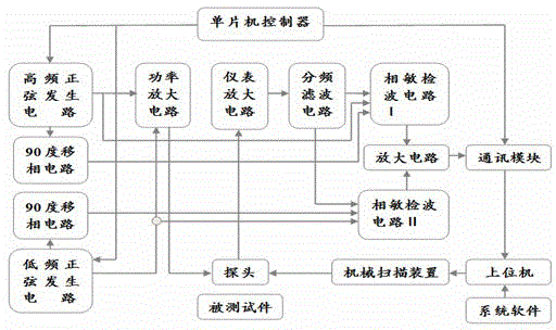
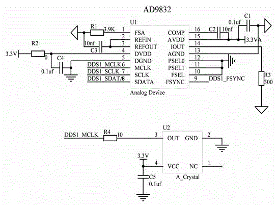
[0029] The integrated chip AD9832 in the high-frequency sinusoidal signal generating circuit and the low-frequency sinusoidal signal generating circuit is controlled by the microcontroller controller to generate high-frequency and low-frequency two-way sine waves. A 90-degree phase shift circuit is added to the circuit to generate high and low frequency signals orthogonal to the excitation signal?

[0030] like Figure 4 As shown, the 90-degree phase-shifting circuit connected to the high-frequency sinusoidal signal generating circuit is composed of the chip OP37 as the core. The first pin of the OP37 chip is connected to the second pin, and the first pin and the second pin of the OP37 chip are connected. Connect to one end of the first resistor R7 and the second resistor R8, the other end of the first resistor R7 is connected to the 6th pin of the OP37 chip, the other end of the second resistor R8 is connected to the 5th pin of the OP37 chip, and the OP37 The 5th pin of the ...


PUM


Abstract

The invention discloses a frequency mixing technology-based metal defect eddy current detection device and a probe structure thereof. According to the device, the conventional eddy current technology and low-frequency far field eddy current technology are combined, so that one-time complete detection on metal material defects in a wider range can be realized. According to the device, a high-frequency excitation signal and a low-frequency excitation signal are applied to the probe; the conventional eddy current detection mode is adopted by the high-frequency signal; and the far field eddy current detection mode is adopted by the low-frequency signal. The probe is of a differential structure and consists of two groups of coils; and the two groups of coils are symmetrically arranged in a mirror image manner. Each group of coils consists of a large coil and a small coil of which the axes are away from each other for a certain distance; and the two coils are placed according to a far field principle. A low-frequency sinusoidal signal is conducted through the large coil in the probe; a high-frequency sinusoidal signal is conducted through the small coil; and the small coil is used as a detection coil to receive the high-frequency signal and the low-frequency signal. According to the device, defect information of an upper surface and a lower surface of a plate-shaped metal material or an inner wall and an outer wall of a tubular metal material can be simultaneously and accurately acquired in a large range.

Description

technical field [0001] The invention relates to frequency mixing technology, a metal material defect non-destructive testing device and a related probe structure. Background technique [0002] The defect detection of metal materials is of great significance in the field of military industry? According to the principle of electromagnetic induction, the coil carrying alternating current will induce eddy current in the metal material close to it, and the induced eddy current will in turn affect the original magnetic field distribution around the detection coil. As a result, the measured impedance of the detection coil changes. The eddy current carries information such as the thickness, defect, and conductivity of the metal material. By measuring the change in coil impedance caused by the eddy current, the relevant physical parameters of the metal material, such as whether there is a defect, can be inferred. [0003] The traditional eddy current detection device has great adva...

Claims


Application Information

Patent Timeline
Patent Type & Authority Applications(China)
IPC IPC(8): G01N27/90G01N27/9013
Inventor 陈佩华黄平捷李国厚周泽魁
Owner ZHEJIANG UNIV
Learn More