
A ranging method and ranging system for eliminating blind spot of lidar

A technology of laser radar and distance measurement method, which is applied in the field of distance measurement system, can solve the problems of diffuse reflection and blind area of ​​protective cover, and achieve the effect of eliminating the blind area of ​​laser radar

Active Publication Date: 2019-12-27
SHENZHEN KYLE OPTICS TECH CO LTD
View PDF6 Cites 0 Cited by
  • Summary
  • Abstract
  • Description
  • Claims
  • Application Information

AI Technical Summary

Problems solved by technology

[0005] The purpose of the present invention is to at least solve the problem of the blind area caused by the diffuse reflection of the protective cover in the above (3), and disclose a distance measuring method and a distance measuring system for eliminating the laser radar blind area

Method used


Image

  • A ranging method and ranging system for eliminating blind spot of lidar
  • A ranging method and ranging system for eliminating blind spot of lidar
  • A ranging method and ranging system for eliminating blind spot of lidar

Examples


Embodiment 1

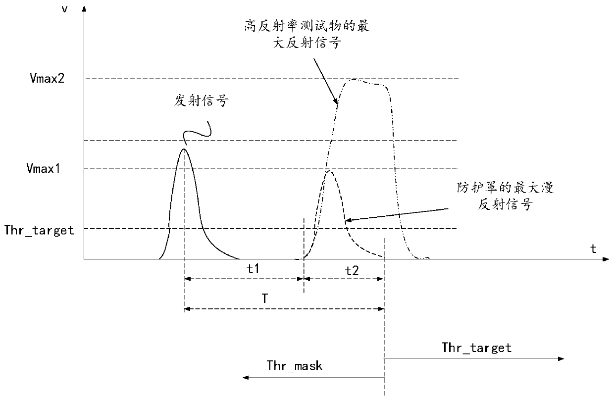
[0039] The embodiment discloses a distance measuring method for eliminating the blind area of ​​the laser radar, which is used for the laser radar with a protective cover. It can be understood that the laser radar has a transmitting module and a receiving module. In order to eliminate the influence of the blind area and improve the accuracy of distance measurement, the protective cover of this embodiment adopts a protective cover that has undergone special treatments such as surface smoothing, coating treatment, and angle treatment; the coating treatment makes the protective cover only for predetermined wavelengths. The laser signal is transmitted, and the included angle is processed so that the specular reflection signal of the protective cover falls outside the field of view of the receiving module, so as to solve the problem of blind spots caused by the specular reflection of the protective cover.

[0040] Specifically, in the system design stage, the predetermined wavelengt...

Embodiment 2

[0056] see Figure 6-Figure 8 , a ranging system for eliminating lidar blind spots disclosed in this embodiment includes a transmitting module 10 , a receiving module 20 , a photoelectric converter 30 , an analog-to-digital converter 40 , a digital signal processor 50 and a protective cover 60 .

[0057] The emitting module 10 emits laser light with a predetermined wavelength as an emitting signal.

[0058] The receiving module 20 receives the reflected reflected signals of respective predetermined wavelengths, and inputs them into the photoelectric converter 30 .

[0059] The photoelectric converter 30 converts the reflected signal from an optical signal into an analog electrical signal, and inputs it into the analog-to-digital converter 40 .

[0060] The analog-to-digital converter 40 converts the electrical signal of the module into a digital signal, and inputs it into a digital signal processor 50 .

[0061] The digital signal processor 50 judges the time value t require...


PUM


Abstract

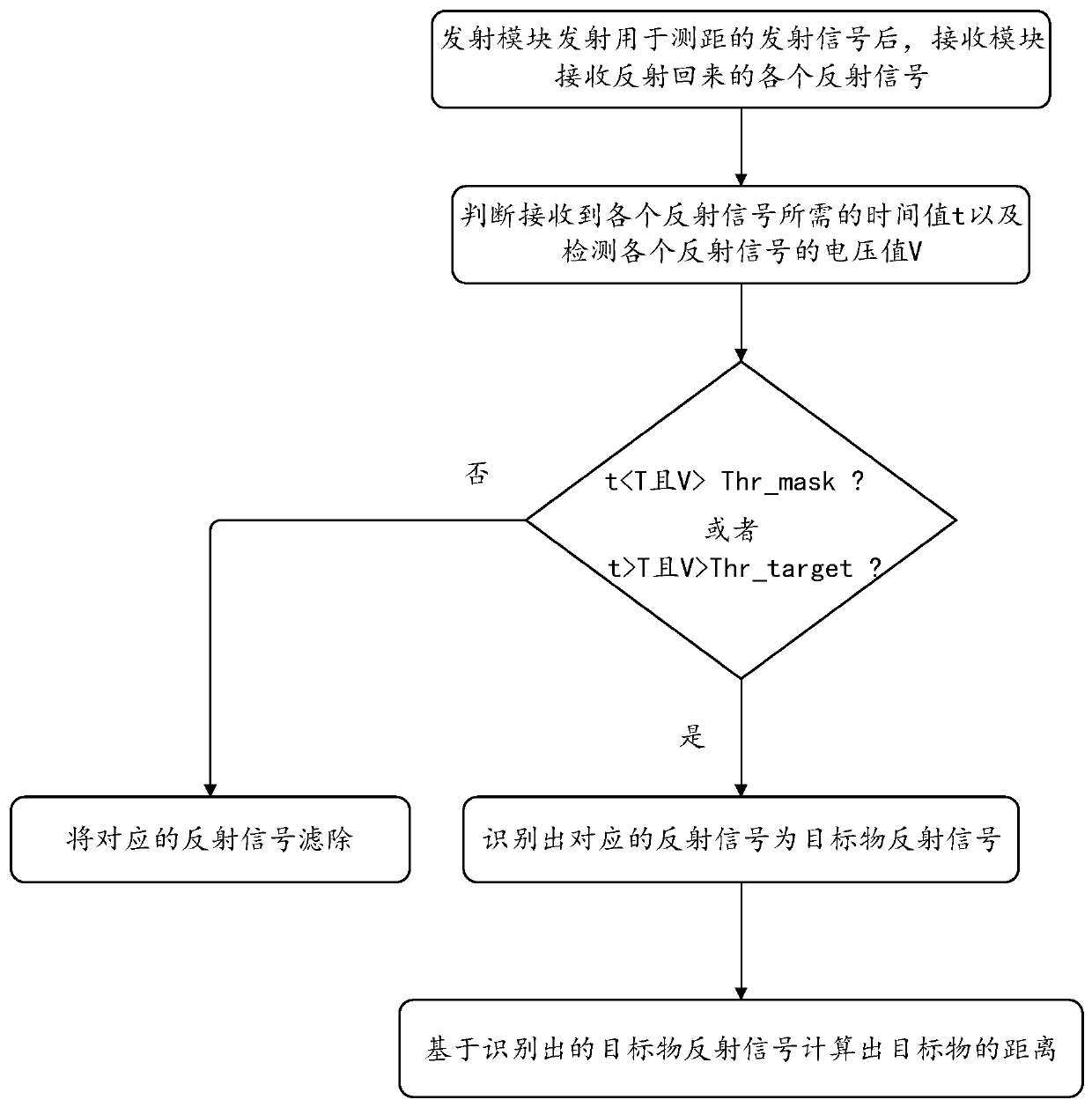
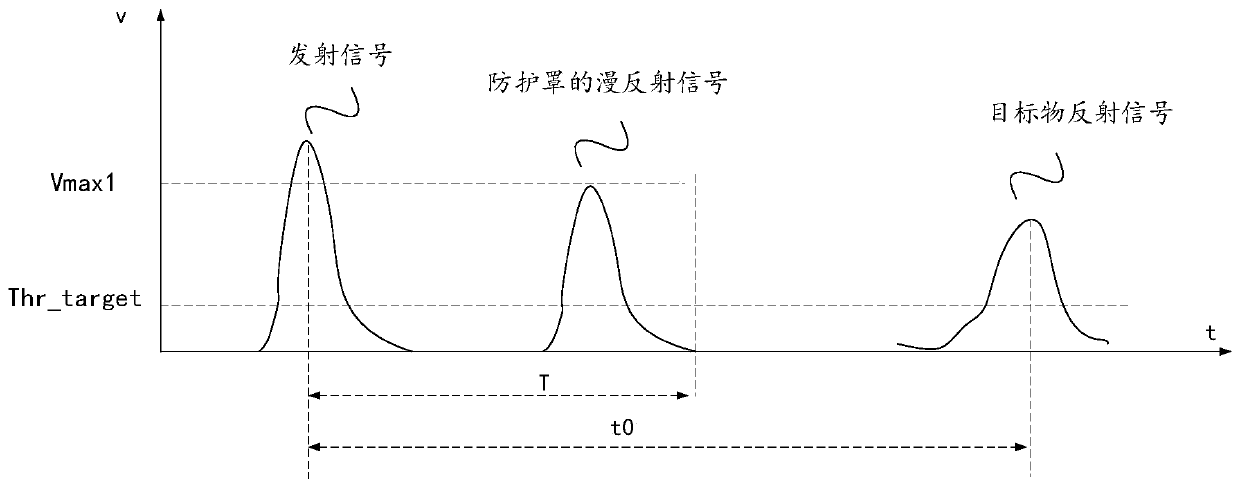
The invention relates to a ranging method and system for eliminating a blind area of a laser radar. The method comprises the following steps that: after a transmitting module transmits a transmittingsignal for ranging, a receiving module receives all reflected signals reflected back; time values t for receiving all reflected signals is determined and voltage values V of all reflected signals aredetected; if the following conditions are met: tThr_mask or t is large than T and V is larger than Thr_mask, the corresponding reflected signal is identified to be a target reflected signal; and on the basis of the identified target reflected signal, a target distance is calculated. Therefore, the influence of the blind area of the laser radar can be eliminated during ranging.

Description

technical field [0001] The invention belongs to the technical field of laser radar ranging with a protective cover, in particular to a ranging method and a ranging system capable of eliminating blind spots caused by a protective cover in a laser radar. Background technique [0002] The general lidar has a near blind area. For example, the maximum range of the lidar is M meters, and the target within n (n<M) meters from the lidar cannot be detected, so there is a blind area of ​​n meters. [0003] There are many reasons for the existence of blind spots, such as: (1) blind spots caused by defects in the system design itself; (2) the processing speed of the lidar system is slow, and the delay from sending out laser signals to receiving effective echoes is too long, resulting in The blind area cannot be detected at a short distance; (3) In the case of a laser radar with a protective cover, the laser signal emitted by the laser radar is reflected on the protective cover, inclu...

Claims


Application Information

Patent Timeline
Patent Type & Authority Patents(China)
IPC IPC(8): G01S7/481G01S17/08
CPCG01S7/481G01S17/08
Inventor 李亚锋张石
Owner SHENZHEN KYLE OPTICS TECH CO LTD
Learn More