Rain gauge for measuring by adopting optical fiber and railway disaster-prevention rainfall monitoring system

A technology of optical fiber measurement and rain gauge, which is applied in the field of rain gauge to achieve the effect of high reliability, guaranteed accuracy and high reliability

Inactive Publication Date: 2013-01-16
BEIJING JIAXUN FEIHONG ELECTRIC CO LTD
View PDF4 Cites 12 Cited by
  • Summary
  • Abstract
  • Description
  • Claims
  • Application Information

AI Technical Summary

Problems solved by technology

However, the existing rainfall monitoring system puts forward higher requirements on the data transmission channel and power supply mode, which further highlights the contradiction that the equipment needs power supply

Method used


Image

  • Rain gauge for measuring by adopting optical fiber and railway disaster-prevention rainfall monitoring system
  • Rain gauge for measuring by adopting optical fiber and railway disaster-prevention rainfall monitoring system
  • Rain gauge for measuring by adopting optical fiber and railway disaster-prevention rainfall monitoring system

Examples


no. 1 example

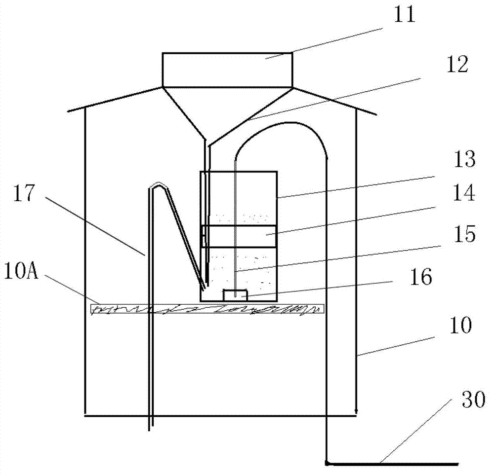
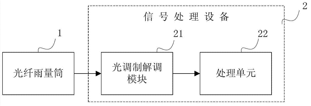
[0030] The siphon rain gauge includes an optical fiber rain gauge 1 and a signal processing device 2 , wherein the optical fiber rain gauge 1 includes an optical fiber sensor 15 , and the optical fiber sensor 15 is connected to the signal processing device 2 through an optical cable 30 . Such as figure 1 As shown, the optical fiber rain gauge 1 has a sealed casing 10, an opening is provided on the top of the casing 10, and a rain bearing 11 is provided. The funnel 12 is located below the rain receiver 11 and is connected with the rain receiver 11 . A support frame 10A is provided in the casing 10 , and the float chamber 13 is provided on the support frame 10A. Of course, the float chamber 13 can also be directly provided at the bottom of the casing 10 . The lower end of the funnel 12 stretches into the bottom of the float chamber 13, and a float 14 is arranged inside the float chamber 13. The float 14 is fixed with the optical fiber sensor 15, and a weight 16 can be fixed bel...

no. 2 example

[0036] The tipping bucket rain gauge includes an optical fiber rain gauge 1 and a signal processing device 2. The structure of the signal processing device 2 in this embodiment is the same as that of the first embodiment, and will not be repeated here.

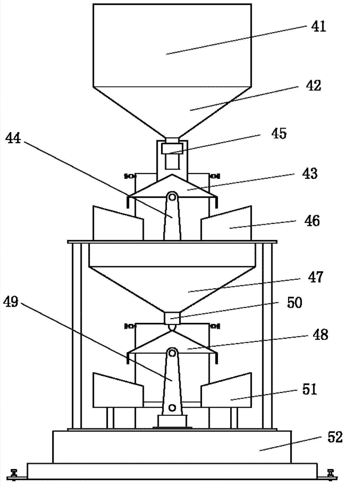
[0037] Such as image 3 As shown, the optical fiber rain gauge 1 includes a rain receiver 41 , a funnel 42 located below the rain receiver 41 and a tipping mechanism 43 located below the funnel 42 . to combine Figure 4 It can be seen that the tipping mechanism 43 has a water separator 43A arranged on the base bracket 44 and two tipping pans 43B respectively arranged on both sides of the water separator 43A, and the tipping mechanism 43 is rotatably connected to the base bracket 44 through a bearing 43C. A reflective mirror 55 is set on the water separator 43A, and the fiber grating sensor 45 is arranged on the outside of the funnel 42 or the fiber grating sensor 45 is arranged at other positions near the water separator 43A....

no. 3 example

[0043] The weighing rain gauge includes an optical fiber rain gauge 1 and a signal processing device 2. The structure of the signal processing device 2 in this embodiment is the same as that of the first embodiment, and will not be repeated here.

[0044] Such as Figure 5 As shown, the optical fiber rain gauge 1 in this embodiment has a sealed casing 70, and at the opening on the upper side of the casing 70, a rain receiver 71 is provided, and the funnel 72 is located below the rain receiver 71 and is connected to the rain receiver 71 , the lower end of the funnel 72 stretches into the water storage tank 73 bottoms. A weighing frame 74 is set in the shell 10, and the water storage tank 73 is arranged above the weighing frame 74. On the weighing frame 74, a position corresponding to the water storage tank 73 is provided with an optical fiber grating sensor 75, and the optical fiber grating sensor 75 weighs by measuring The amount of deformation of the measuring frame 74 under...


PUM


Abstract

The invention discloses a rain gauge for measuring by adopting an optical fiber and a railway disaster-prevention rainfall monitoring system. The rain gauge comprises an optical fiber rainfall cylinder and a signal processing device, wherein the optical fiber rainfall cylinder comprises an optical fiber sensor, and the optical fiber sensor is connected with the signal processing device through an optical cable. The railway disaster-prevention rainfall monitoring system comprises a plurality of optical fiber rainfall cylinders and a signal processing device, wherein the optical fiber rainfall cylinders are distributed at different rainfall monitoring points, the signal processing device is arranged at a monitoring center, and the plurality of optical fiber rainfall cylinders are connected with the signal processing device through the optical cable. According to the rain gauge and the railway disaster-prevention rainfall monitoring system provided by the invention, the rainfall is measured by the combination of the optical fiber sensor and mechanical parts, not only is the passivity of a measuring device realized at the rainfall monitoring point, the remote power supplying is unnecessary, but also the signal is transmitted by the optical cable, and the interferences of outside signals can be avoided, so that the anti-jamming capacity is strong and the reliability is high.

Description

technical field [0001] The invention relates to a rain gauge for measuring rainfall, in particular to a rain gauge using an optical fiber measurement method. The invention also relates to a railway disaster prevention rainfall monitoring system using the rain gauge. Background technique [0002] In the prior art, commonly used rain gauges are mainly mechanical rain gauges, one of which is a siphon rain gauge and the other is a tipping bucket rain gauge. In addition, there are a small number of radar rain gauges, optical rain gauges and pressure rain gauges. In actual use, siphon rain gauges and tipping bucket rain gauges are the majority. Among them, the siphon rain gauge counts the rainfall by measuring the height change of the float in the float chamber and the number of siphons, while the tipping bucket rain gauge realizes the rainfall statistics by recording the preset value of the tipping bucket and the number of turning times of the tipping bucket. In the above-menti...

Claims


Application Information

Patent Timeline
Patent Type & Authority Applications(China)
IPC IPC(8): G01W1/14G08C23/06
Inventor 冯军
Owner BEIJING JIAXUN FEIHONG ELECTRIC CO LTD
Why Eureka
Try Eureka