Rain gauge and railway disaster prevention rainfall monitoring system using optical fiber measurement
A technology of optical fiber measurement and siphon rain gauge, which is applied in the field of rain gauge to achieve the effect of ensuring accuracy, high reliability and high reliability
- Summary
- Abstract
- Description
- Claims
- Application Information
AI Technical Summary
Problems solved by technology
Method used
Image
Examples
no. 1 example
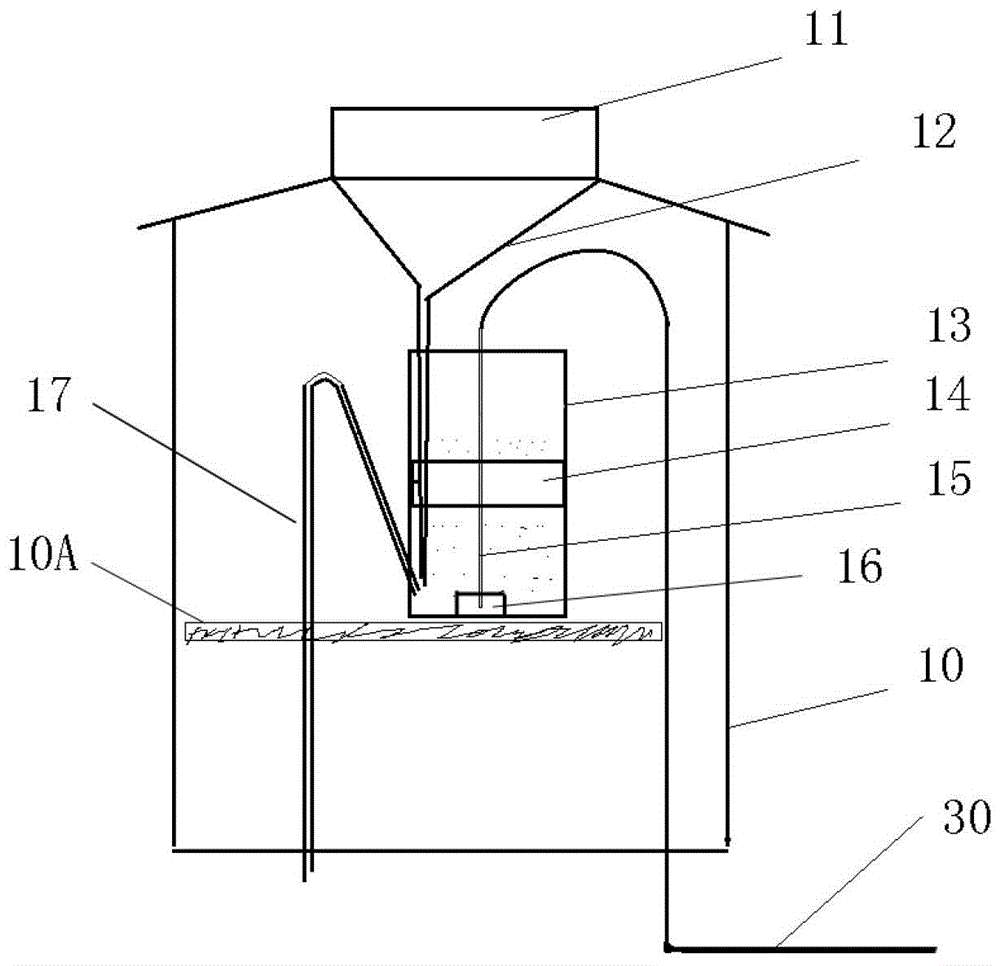
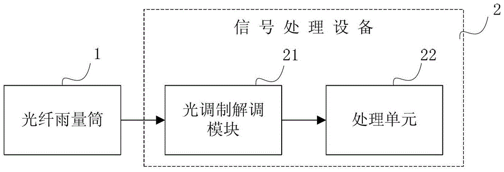
[0030] The siphon rain gauge includes an optical fiber rain gauge 1 and a signal processing device 2 , wherein the optical fiber rain gauge 1 includes an optical fiber sensor 15 , and the optical fiber sensor 15 is connected to the signal processing device 2 through an optical cable 30 . Such as figure 1 As shown, the optical fiber rain gauge 1 has a sealed casing 10, an opening is provided on the top of the casing 10, and a rain bearing 11 is provided. The funnel 12 is located below the rain receiver 11 and is connected with the rain receiver 11 . A support frame 10A is provided in the casing 10 , and the float chamber 13 is provided on the support frame 10A. Of course, the float chamber 13 can also be directly provided at the bottom of the casing 10 . The lower end of the funnel 12 stretches into the bottom of the float chamber 13, and a float 14 is arranged inside the float chamber 13. The float 14 is fixed with the optical fiber sensor 15, and a weight 16 can be fixed bel...
no. 2 example
[0036] The tipping bucket rain gauge includes an optical fiber rain gauge 1 and a signal processing device 2. The structure of the signal processing device 2 in this embodiment is the same as that of the first embodiment, and will not be repeated here.
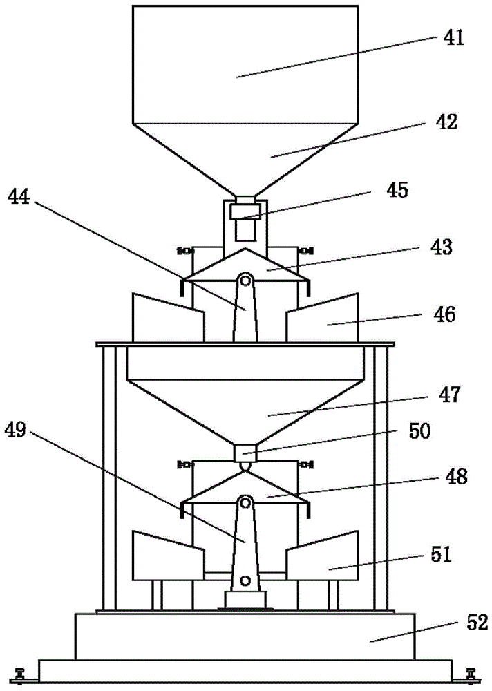
[0037] Such as image 3 As shown, the optical fiber rain gauge 1 includes a rain receiver 41 , a funnel 42 located below the rain receiver 41 and a tipping mechanism 43 located below the funnel 42 . combine Figure 4 It can be seen that the tipping mechanism 43 has a water separator 43A arranged on the base bracket 44 and two tipping pans 43B respectively arranged on both sides of the water separator 43A, and the tipping mechanism 43 is rotatably connected to the base bracket 44 through a bearing 43C. A reflective mirror 55 is set on the water separator 43A, and the fiber grating sensor 45 is arranged on the outside of the funnel 42 or the fiber grating sensor 45 is arranged at other positions near the water separator 43A. Th...
no. 3 example
[0043] The weighing rain gauge includes an optical fiber rain gauge 1 and a signal processing device 2. The structure of the signal processing device 2 in this embodiment is the same as that of the first embodiment, and will not be repeated here.
[0044] Such as Figure 5 As shown, the optical fiber rain gauge 1 in this embodiment has a sealed casing 70, and at the opening on the upper side of the casing 70, a rain receiver 71 is provided, and the funnel 72 is located below the rain receiver 71 and is connected to the rain receiver 71 , the lower end of the funnel 72 stretches into the water storage tank 73 bottoms. A weighing frame 74 is set in the shell 10, and the water storage tank 73 is arranged above the weighing frame 74. On the weighing frame 74, a position corresponding to the water storage tank 73 is provided with an optical fiber grating sensor 75, and the optical fiber grating sensor 75 weighs by measuring The amount of deformation of the measuring frame 74 under...
PUM
 Abstract
Description
Claims
Application Information
 - R&D
- Intellectual Property
- Life Sciences
- Materials
- Tech Scout
- Unparalleled Data Quality
- Higher Quality Content
- 60% Fewer Hallucinations
Browse by: Latest US Patents, China's latest patents, Technical Efficacy Thesaurus, Application Domain, Technology Topic, Popular Technical Reports.
© 2025 PatSnap. All rights reserved.Legal|Privacy policy|Modern Slavery Act Transparency Statement|Sitemap|About US| Contact US: help@patsnap.com


