Multifunctional wall-mounted power supply device

A power supply device and multi-functional technology, applied in the direction of circuit devices, battery circuit devices, load supply circuits, etc., can solve problems such as long working cycle, inability to ensure effective and real-time information exchange, hidden dangers of construction safety, etc., to achieve large construction volume , to achieve long-term stable supply and ensure long-term effects

Pending Publication Date: 2018-04-27
济南热力集团有限公司
View PDF0 Cites 0 Cited by
  • Summary
  • Abstract
  • Description
  • Claims
  • Application Information

AI Technical Summary

Problems solved by technology

[0002] In the process of project construction, it is necessary to ensure real-time communication between external personnel and on-site staff through information transmission in a timely manner. For example, construction projects such as underground pipe corridors have long work cycles and difficult construction, and are prone to construction safety hazards, requiring on-site work The personnel exchange information and communicate with relevant external personnel in a timely manner to ensure the safety of on-site work and effective monitoring of on-site information. However, due to the inconvenient power supply at the construction site and the poor network signal in the relatively closed space, or even no network signal at all, it is difficult to It can ensure the effective and real-time information exchange between the construction site and the outside world, resulting in a delay in receiving information from both parties, causing inconvenience to safety production, on-site monitoring and dispatching command, and prone to safety hazards

Method used


Image

  • Multifunctional wall-mounted power supply device
  • Multifunctional wall-mounted power supply device
  • Multifunctional wall-mounted power supply device

Examples


Embodiment Construction

[0031] In order to better understand the present invention, the implementation manner of the present invention will be explained in detail below in conjunction with the accompanying drawings.

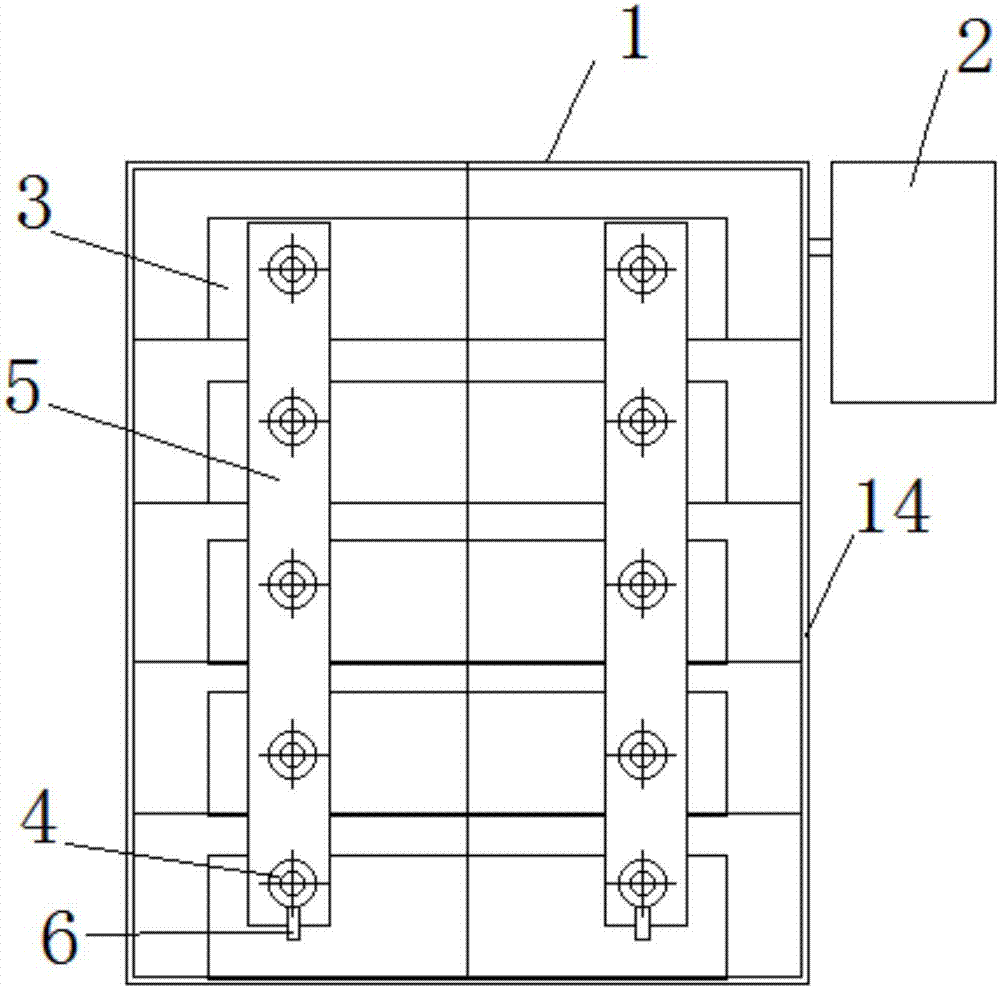
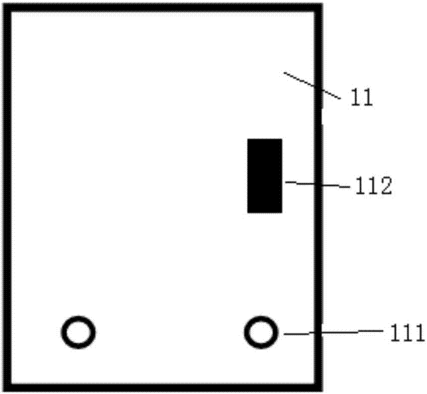
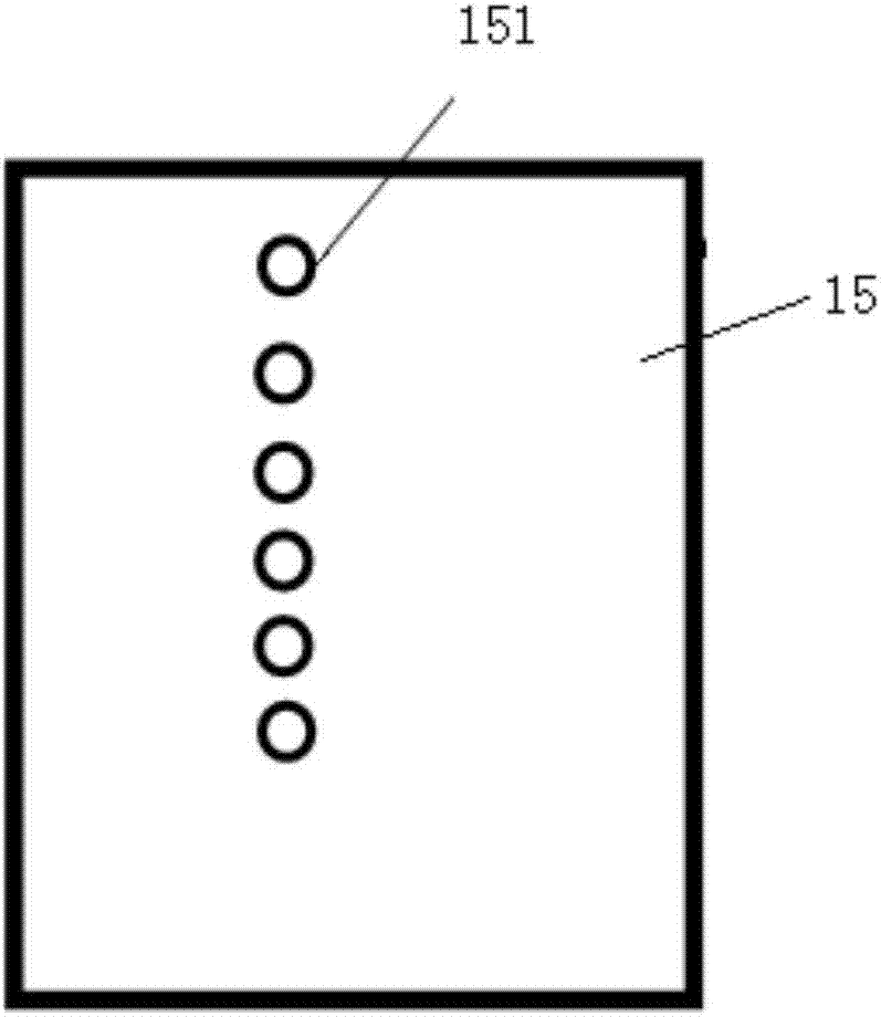
[0032] combine Figure 1 to Figure 10 , a multifunctional wall-mounted power supply device, comprising a main box body 1, an auxiliary box body 2, the main box body 1 includes a support frame 17, and a front guard plate 11, a rear guard plate 15, and an upper case cover respectively connected to the support frame 12. The lower guard plate 16, the left guard plate 13, the right guard plate 14, the front guard plate 11, the rear guard plate 15, the upper box cover 12, the lower guard plate 16, the left guard plate 13, the right guard plate 14 and the support frame respectively Connect to form a sealed box structure, the main box is provided with a number of batteries 3 from top to bottom, and the batteries are connected in parallel through the battery positive and negative terminals 4 and...


PUM


Abstract

The invention discloses a multifunctional wall-mounted power supply device, which includes a main box body and an auxiliary box body. On the right guard plate, several batteries are arranged from top to bottom in the main box, the positive and negative terminals of the battery at the lower part are provided with extension terminals, the lower part of the front guard plate is provided with the protruding openings of the extension terminal posts, the front guard plate and the left guard plate Connected by a hinged shaft, the upper cover of the main box is provided with a mounting hole, the left guard is provided with a camera bracket installation port, the auxiliary box is connected to the upper side of the right guard, and a wireless relay device is installed in the auxiliary box , the camera, the wireless relay device and the battery are electrically connected, and the wireless relay device and the remote control terminal perform signal transmission. The invention can continuously video-monitor the construction site without electric network signal, realize the external signal introduction to the area with poor network environment, and solve the problems of difficult construction site management and remote supervision construction.

Description

technical field [0001] The invention relates to the technical field of power supply equipment, in particular to a multifunctional wall-mounted power supply device, which is applied to indoor and outdoor areas that do not have power supply conditions, to achieve continuous operation of low-power electrical equipment, and to realize functions such as video monitoring and network relay. Background technique [0002] In the process of project construction, it is necessary to ensure real-time communication between external personnel and on-site staff through information transmission in a timely manner. For example, construction projects such as underground pipe corridors have long work cycles and difficult construction, and are prone to construction safety hazards, requiring on-site work The personnel exchange information and communicate with relevant external personnel in a timely manner to ensure the safety of on-site work and effective monitoring of on-site information. However...

Claims


Application Information

Patent Timeline
Patent Type & Authority Applications(China)
IPC IPC(8): H02J7/00H04N7/18H04B7/155H02J7/35H02J7/14
CPCH02J7/0042H02J7/0063H02J7/1423H02J7/35H04B7/155H04N7/18
Inventor 吕呈龙徐军丁鑫
Owner 济南热力集团有限公司
Why Eureka
Try Eureka