Vertical alignment (VA) display mode compensation framework and VA display mode liquid crystal display device

A liquid crystal display device and display mode technology, applied in optics, instruments, nonlinear optics, etc., can solve the problems of affecting the viewing effect, low contrast, high price, etc., to increase contrast and clarity, improve contrast and clarity, The effect of light leakage reduction in dark state

Active Publication Date: 2013-01-16
SHENZHEN CHINA STAR OPTOELECTRONICS TECH CO LTD
View PDF3 Cites 6 Cited by
  • Summary
  • Abstract
  • Description
  • Claims
  • Application Information

AI Technical Summary

Problems solved by technology

In order to improve the viewing effect, double-layer biaxial compensation film compensation should be used, but its price is relatively expensive, which is not conducive to reducing costs
Although the use of single-layer biaxial compensation film compensation can effectively reduce the cost, but the light leakage in the dark state near the horizontal viewing angle is serious, and the contrast is low, which affects the viewing effect.

Method used


Image

  • Vertical alignment (VA) display mode compensation framework and VA display mode liquid crystal display device
  • Vertical alignment (VA) display mode compensation framework and VA display mode liquid crystal display device
  • Vertical alignment (VA) display mode compensation framework and VA display mode liquid crystal display device

Examples


Embodiment Construction

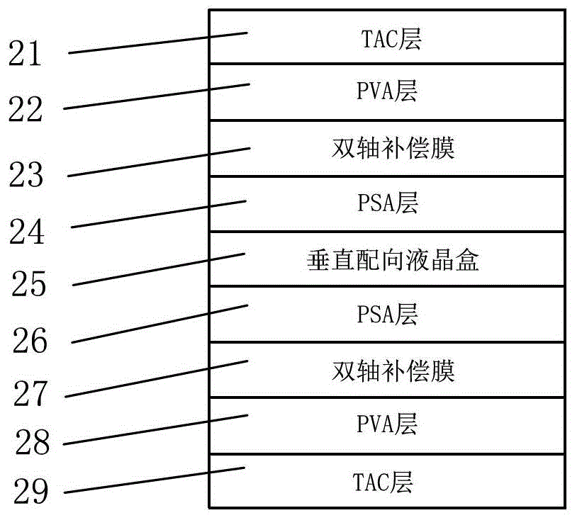
[0042] Such as Figure 4 As shown, it is a schematic diagram of the VA display mode compensation structure and its slow axis and absorption axis angle settings of the present invention. The VA display mode compensation structure of the present invention mainly includes a first TAC layer 41, a first PVA layer 42, a biaxial compensation film 43, a vertically aligned liquid crystal cell 45, a second TAC layer 47, and a second PVA layer arranged sequentially from top to bottom. Layer 48 and the third TAC layer 49 are based on the horizontal viewing angle direction of 0 degree of the vertically aligned liquid crystal cell 45, the absorption axis of the first PVA layer 42 is set at 0 degree, and the slow axis of the biaxial compensation film 43 is set at 90° The slow axis of the second TAC layer 47 is set at 0 degrees, and the absorption axis of the second PVA layer 48 is set at 90 degrees. This preferred embodiment changes the compensation structure of the existing single-layer bi...


PUM

PropertyMeasurementUnit
hysteresis lossaaaaaaaaaa

Abstract

The invention relates to a VA display mode compensation framework and a VA display mode liquid crystal display device. The VA display mode compensation framework comprises a first triacetyl cellulose (TAC) layer, a first polarization layer, a dual-axis compensation film, a vertical alignment liquid crystal cell, a second TAC layer, a second polarization layer and a third TAC layer which are arranged sequentially from top to bottom, the horizontal view angle zero-degree direction of the vertical alignment liquid crystal cell (that is, a VA liquid crystal display) serves as the reference, an absorbing axis of the first polarization layer is at an angle of 0 degree, a slow axis of the dual-axis compensation film is at an angle of 90 degrees, a slow axis of the second TAC layer is at an angle of 0 degree, and an absorbing axis of the second polarization layer is at an angle of 90 degrees. By the aid of the VA display mode compensation framework and the VA display mode liquid crystal display device, view angles which are severe in dark state light leakage are deflected towards a vertical view angle, the contrast ratio and the definition of the horizontal view angle are improved, and the ideal dark state light leakage effect can be achieved through ideal matching of compensation values of a single layer of the dual-axis compensation film and compensation values of TAC layers.

Description

technical field [0001] The present invention relates to a liquid crystal display device, in particular to a VA (vertical alignment) display mode compensation structure and a VA display mode liquid crystal display device. Background technique [0002] TFT (Thin Film Transistor)-LCD is a thin film transistor LCD, which is a kind of active matrix liquid crystal display (AM-LCD). Liquid crystal flat panel display, especially TFT-LCD, is currently the only display device that has fully caught up with and surpassed CRT in terms of brightness, contrast, power consumption, life, volume and weight. It has excellent performance and large-scale production characteristics. With high degree of automation, low cost of raw materials and broad development space, it will quickly become a mainstream product in the new century and a bright spot of global economic growth in the 21st century. [0003] However, as the viewing angle of TFT-LCD increases, the contrast of the screen decreases conti...

Claims


Application Information

Patent Timeline
Patent Type & Authority Applications(China)
IPC IPC(8): G02F1/1337G02F1/13363
CPCG02F2413/05G02B5/3025G02F2001/133742G02F1/13363G02F2001/133531G02F2413/12G02F1/133531G02F1/133742
Inventor 康志聪海博
Owner SHENZHEN CHINA STAR OPTOELECTRONICS TECH CO LTD
Why Eureka
Try Eureka