Stabilized power circuit used in high-voltage direct current-direct current (DC-DC) converter

A stabilized power supply circuit, DC-DC technology, applied in the direction of instruments, adjusting electrical variables, control/regulation systems, etc., to achieve the effect of suppressing mutual interference and solving startup problems

Active Publication Date: 2013-01-16
深圳德信微电子有限公司
View PDF11 Cites 2 Cited by
  • Summary
  • Abstract
  • Description
  • Claims
  • Application Information

AI Technical Summary

Problems solved by technology

[0005] The purpose of the present invention is to solve the power supply problem of the low-voltage circuit inside the existing high-voltage DC-DC converter, and propose a voltage-stabilizing power supply circuit applied to the inside of the high-voltage DC-DC converter to generate four groups of mutually isolated and non-interfering The internal regulated power supply of the chip supplies power to the analog module, digital module, power module and bootstrap capacitor respectively, so that the internal power supplies are independent of each other and do not interfere with each other when the chip is working normally.

Method used


Image

  • Stabilized power circuit used in high-voltage direct current-direct current (DC-DC) converter
  • Stabilized power circuit used in high-voltage direct current-direct current (DC-DC) converter
  • Stabilized power circuit used in high-voltage direct current-direct current (DC-DC) converter

Examples


Embodiment Construction

[0044] The present invention will be further described below in conjunction with accompanying drawings and embodiments thereof.

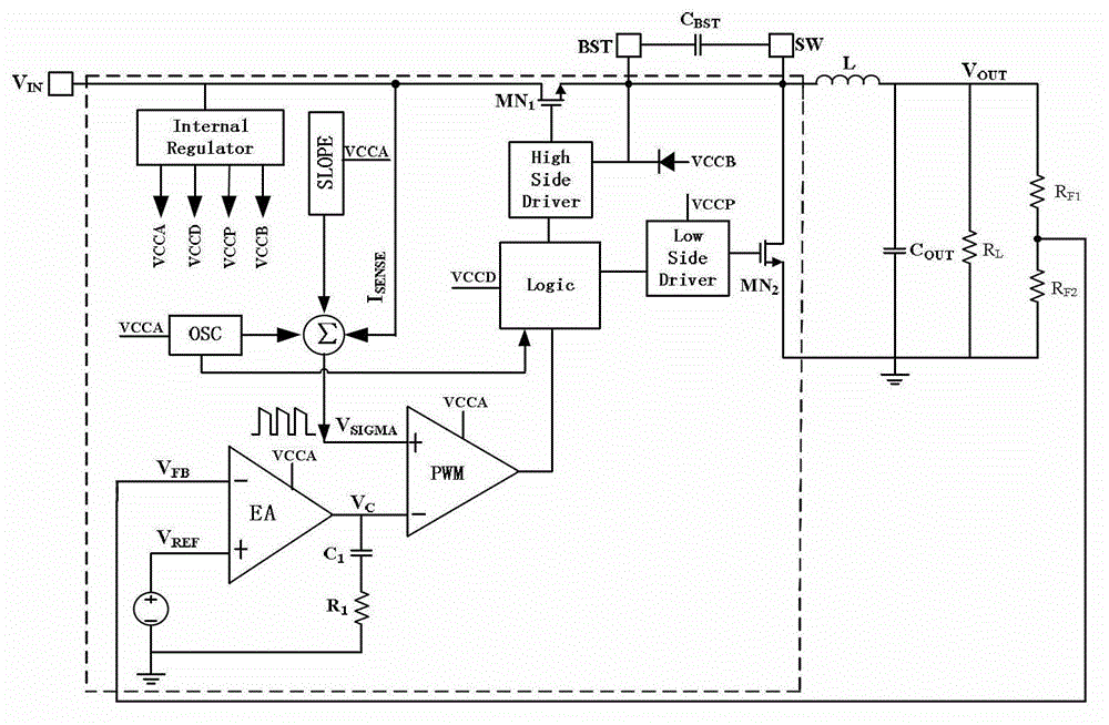
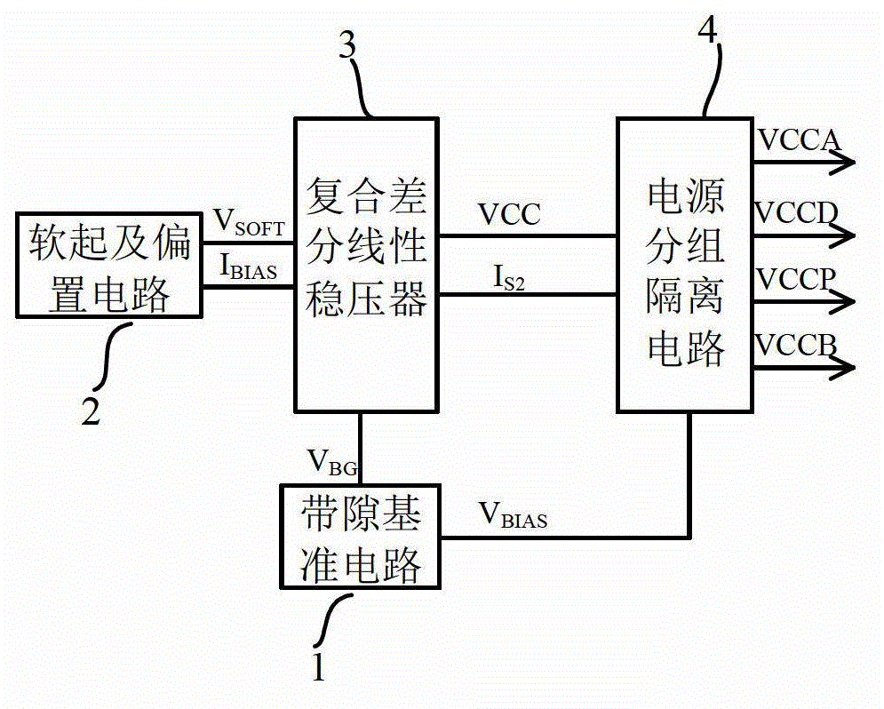
[0045] refer to image 3 , the stabilized power supply circuit of the present invention includes: a bandgap reference circuit 1, a soft start and bias circuit 2, a composite differential input linear regulator 3 and a power group isolation circuit 4, wherein: the bandgap reference circuit 1 is used to produce a reference voltage with zero temperature coefficient V BG and bias voltage V BIAS , the reference voltage V BG Connected to the composite differential input linear regulator 3 to provide a reference voltage for the composite differential input linear regulator 3 during normal operation, the bias voltage V BIAS Connected to the power group isolation circuit 4 to provide voltage bias for some low-voltage NMOS in the power group isolation circuit 4; the soft start and bias circuit 2 is used to generate the soft start voltage V SOFT and bias c...


PUM


Abstract

The invention discloses a stabilized power circuit used in a high-voltage direct current-direct current (DC-DC) converter. The problem of interference between internal power supplies of the conventional converter is mainly solved. The stabilized power circuit comprises a band-gap reference circuit (1), a soft start and bias circuit (2), a combined differential linear voltage stabilizer (3) and a power grouping isolation circuit (4), wherein the band-gap reference circuit (1) is used for generating current and soft starting voltage VSOFT; the soft start voltage VSOFT provides reference voltage for the combined differential linear voltage stabilizer (3) before reference voltage VBR is set, and rough internal analogue power VCCA is generated through the power grouping isolation circuit (4) to enable the band-gap reference circuit (1) to work; after the reference voltage VBG is set, the combined differential linear voltage stabilizer (3) automatically switches the reference voltage from the soft start voltage VSOFT to the reference voltage VBG to generate an accurate voltage signal VCC, and transmits the VCC to the power grouping isolation circuit (4); and by the conversion of the power grouping isolation circuit (4), four paths of non-interfering internal power are output, and are supplied to the analogue module, the digital module, a power module and a bootstrap capacitor in the converter. The internal power is non-interfering when a chip normally works.

Description

technical field [0001] The invention belongs to the technical field of electronic circuits and relates to a voltage-stabilizing power supply circuit, which can be used in high-voltage DC-DC converters. Background technique [0002] Switching integrated DC-DC converters are the preferred solution for power management in automotive electronics due to their high efficiency. However, the application requirements of wide input voltage and wide load range of automotive electronics have brought new challenges to the design of converters. For general high-voltage DC-DC converters, two power supplies, high and low, are required. The high input power supplies power for the internal high-voltage drive and related modules, while the low-voltage internal power supply supplies power for the internal low-voltage modules. In this way, a power supply needs to be generated inside the chip. High voltage to low voltage power supply. [0003] figure 1 It shows the system block diagram of the ...

Claims


Application Information

Patent Timeline
Patent Type & Authority Applications(China)
IPC IPC(8): G05F1/56
Inventor 来新泉李演明徐灵炎邵丽丽
Owner 深圳德信微电子有限公司
Why Eureka
Try Eureka