Dynamical joint simulation analysis method of door system of rail transit vehicle

A rail transit vehicle and co-simulation technology, applied in the field of co-simulation analysis of rail vehicle door system dynamics, can solve problems such as unreported simulation analysis of rail vehicle door systems, achieve low-cost design goals, reduce risks, and high economic benefits Effect

Active Publication Date: 2013-01-16
NANJING KANGNI MECHANICAL & ELECTRICAL +1
View PDF2 Cites 30 Cited by
  • Summary
  • Abstract
  • Description
  • Claims
  • Application Information

AI Technical Summary

Problems solved by technology

According to the literature search, based on the virtual prototype technology, the simulatio...

Method used


Image

  • Dynamical joint simulation analysis method of door system of rail transit vehicle
  • Dynamical joint simulation analysis method of door system of rail transit vehicle
  • Dynamical joint simulation analysis method of door system of rail transit vehicle

Examples


Embodiment 1

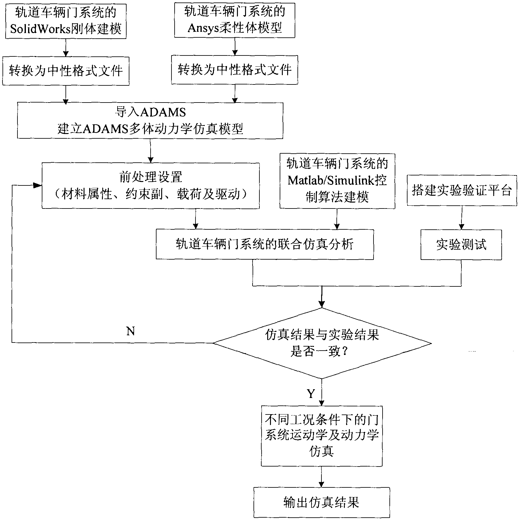
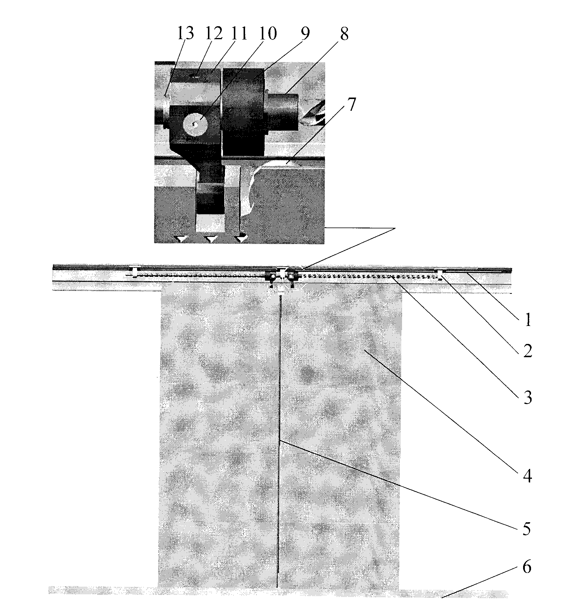
[0060] This embodiment is used for the dynamic joint simulation analysis method of the rail vehicle door system, and the flow chart of the simulation analysis method is as follows figure 1 shown. The components of the rail vehicle door system involved include such as figure 2 parts shown.

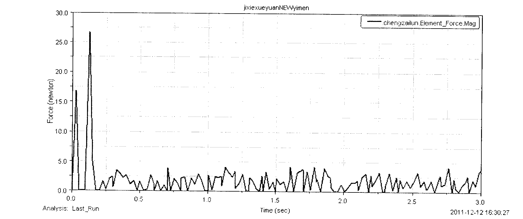
[0061] In this embodiment, by simulating the door opening process of the rail transit vehicle door system, the force situation of the load-carrying wheel is output during the door-opening process, and the force situation of the load-carrying wheel in the three-dimensional direction of space can be output through the force of the load-carrying wheel. The fatigue life is analyzed, and the reliability design of the load wheel is carried out, which provides an important theoretical basis for the optimal design of the load wheel.

[0062] In the use of the embodiment of the present invention of the above-mentioned experimental research, the basic flow is as follows:

[0063] The first step i...

Embodiment 2

[0069] This embodiment is used for the dynamic joint simulation analysis method of the rail transit vehicle door system, and the flow chart of the simulation analysis method is as follows figure 1 shown. The components of the rail vehicle door system involved include such as figure 2 parts shown.

[0070] In this embodiment, by simulating the door opening process of the rail vehicle door system, the displacement, velocity, and acceleration curves of the door panel during the door opening process are output to evaluate the stability of the rail vehicle door system. The force condition of the rolling lock pin in the key components of the rail transit vehicle door system is output, which is used for the operation safety evaluation of the rail transit vehicle door system, and provides an important theoretical basis for the optimal design of key components in the rail transit vehicle door system.

[0071] In the use of the embodiment of the present invention of the above-mention...


PUM

PropertyMeasurementUnit
Stiffnessaaaaaaaaaa
Stiffnessaaaaaaaaaa

Abstract

The invention mainly relates to a dynamical joint simulation analysis method of a door system of a rail transit vehicle, and the method mainly comprises the steps as follows: (1) a system is subjected to three-dimensional modeling and a three-dimensional model is converted to a neutral file in a SolidWorks environment to be imported into ADAMS (automatic dynamic analysis of mechanical systems); (2) the modal analysis of a flexible body component is conducted in Ansys, and converted to a neutral file to be imported into the ADAMS to replace a corresponding rigid body model; (3) a simulation model is preprocessed; (4) a system control model is built in Matlab, the door system is subjected to simulation control by an ADAMS/Control module to accomplish the kinematic and dynamical simulations of the whole system; (5) an experimental test platform is constructed, and a motion experimental test of the system is conducted; (6) a simulation result is compared with an experimental result, and the model is modified continuously; and (7) motion simulations of opening and closing a door and simulating a practical operating condition are conducted to search an optimal door control system mode.

Description

technical field [0001] The invention relates to an analysis method for co-simulation by using SolidWorks, Ansys, ADAMS and Matlab, in particular to a co-simulation analysis method for dynamics of a rail vehicle door system. Background technique [0002] With the rapid development of rail transportation, the demand for rail vehicles is increasing year by year. As a key large-scale component in the rail vehicle system, the design of the rail vehicle door system has aroused great attention from the rail vehicle design, operation and transportation management departments. The safety of rail vehicle door systems directly affects the safety of rail vehicles. In recent years, the reliability design of high-speed vehicle systems has become one of the important topics studied by scholars at home and abroad. [0003] The traditional method of track door system design is to first analyze the requirements of the door system, then produce and develop a prototype, and then carry out the w...

Claims


Application Information

Patent Timeline
IPC IPC(8): G06F17/50
Inventor 朱松青史翔韩亚丽许有熊陈茹雯贡智兵
Owner NANJING KANGNI MECHANICAL & ELECTRICAL
Why Eureka
Try Eureka