Multifrequency antenna

A multi-frequency antenna and dielectric substrate technology, applied in the field of multi-frequency communication, can solve the problems of unfavorable small-scale production and installation, complex manufacturing process, etc., and achieve the effect of three-frequency working characteristics, easy production, and good impedance matching

Active Publication Date: 2013-01-16
SUN YAT SEN UNIV
View PDF9 Cites 7 Cited by
  • Summary
  • Abstract
  • Description
  • Claims
  • Application Information

AI Technical Summary

Problems solved by technology

The antenna has the following disadvantages: the manufacturing process is relatively complicated, which is not conducive to small-scale production and installation

Method used


Image

  • Multifrequency antenna
  • Multifrequency antenna
  • Multifrequency antenna

Examples


Embodiment 1

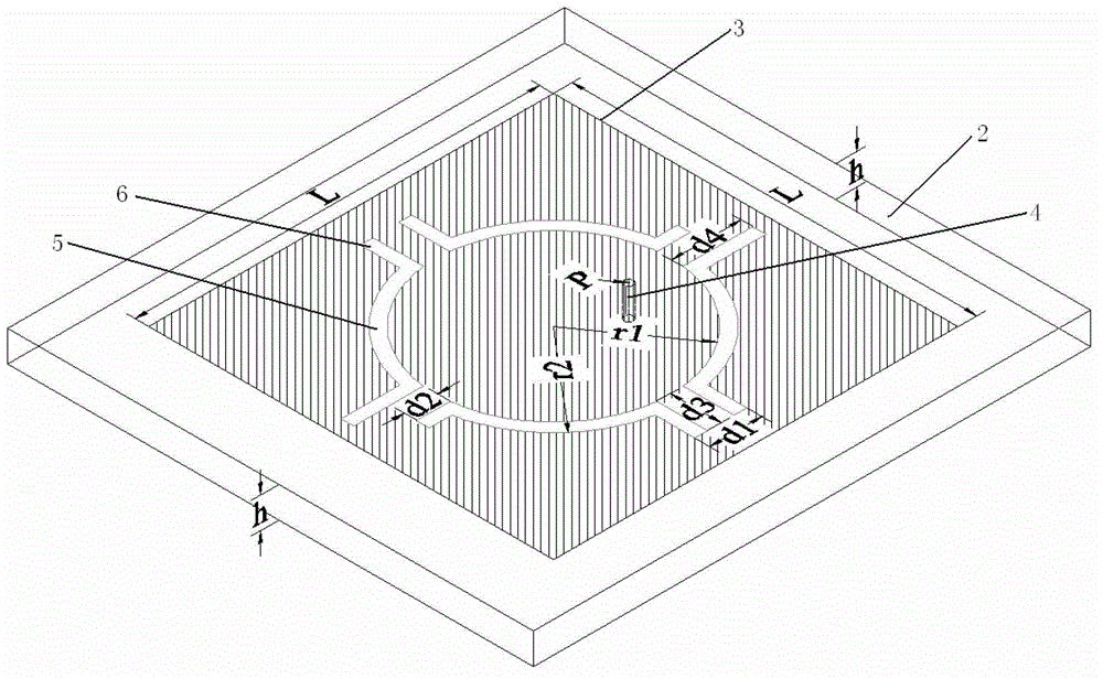
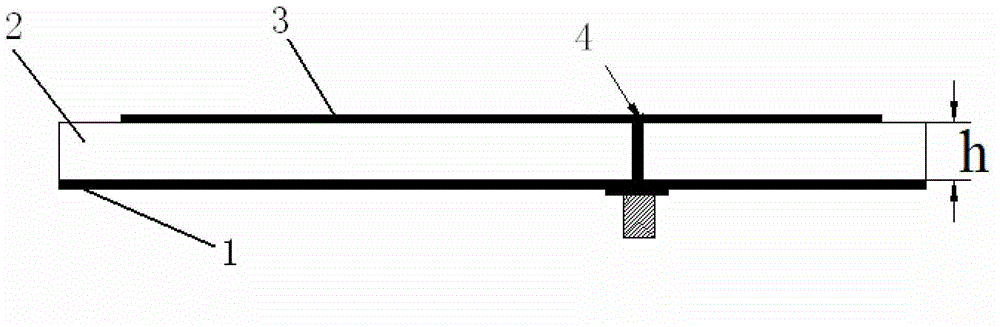
[0034] Such as figure 1 As shown, a multi-frequency antenna includes a lower metal ground plate, a dielectric substrate, a radiation patch and a feed connector, the dielectric substrate is set on the lower metal ground plate, the radiation patch is set on the dielectric substrate, and the feed connector The feed pin in the center is connected to the radiation patch, and the ground end of the feed connector is connected to the lower metal ground plate; there are four arc-shaped gaps on the radiation patch, and these four arc-shaped gaps are on the same circumference Evenly distributed, along the two symmetrical lines of the four arc-shaped slots, a rectangular slot is also opened at the end of each arc-shaped slot.

[0035] The radiation patch is a square, and its side length reference value L is calculated by the following formula:

[0036] L = 1 2 f r ...


PUM


Abstract

The invention discloses a multifrequency antenna which comprises a lower metal earth plate, a medium substrate, a radiation patch and a feed connector. The medium substrate is arranged on the lower metal earth plate, the radiation patch is arranged on the medium substrate, a feed needle at the center of the feed connector is connected with the radiation patch, and an earth terminal of the feed connector is connected with the lower metal earth plate. The radiation patch is provided with four arc slots, the four arc slots are uniformly distributed on the same circumference, and rectangular slots are further arranged at ends of the arc slots along two symmetric lines of the four arc slots. The multifrequency antenna is easy in processing, manufacturing and mounting, is capable of realizing better impedance matching, can be applied to various systems such as GSM (global system for mobile communications) / 3G (the 3rd generation telecommunication) / WLAN (wireless local area network). By the aid of two pairs of arc slots and four pairs of convex slots on the outer side of the patch of a plane slot antenna, current distribution on the surface of the patch can be changed, three resonance points can be excited, and three-frequency operating characteristic can be achieved.

Description

technical field [0001] The invention relates to the technical field of multi-frequency communication, in particular to a multi-frequency antenna. Background technique [0002] With the introduction of various wireless communication standards, such as from GSM to 3G, WLAN, etc., a multi-frequency transceiver system that can work in multiple frequency bands at the same time has emerged, which greatly improves the integrated development of communication systems. As an indispensable key component in multi-frequency transceivers, multi-frequency antennas have been widely researched and applied. Using multi-frequency antennas can be applied to communication systems that send / receive radio signals in multiple frequency bands. Compared with using multiple single-frequency The antenna has the advantages of compactness, simple implementation and low cost. [0003] Most of the existing multi-frequency communication antennas adopt a multi-layer structure and a three-dimensional structu...

Claims


Application Information

Patent Timeline
IPC IPC(8): H01Q13/10H01Q5/01H01Q1/38H01Q5/10
Inventor 李元新陈文宽龙云亮
Owner SUN YAT SEN UNIV
Why Eureka
Try Eureka