Hall position sensor-based position estimation and compensation method for permanent magnet synchronous motor

A technology of permanent magnet synchronous motor and Hall position, which is applied in the direction of torque ripple control, etc., can solve the problems of installation accuracy, symmetry, and error, and achieve the effect of reducing torque ripple and noise, and reducing waveform distortion

Active Publication Date: 2013-01-16
DONGFANG ELECTRIC CORP LTD
View PDF5 Cites 38 Cited by
  • Summary
  • Abstract
  • Description
  • Claims
  • Application Information

AI Technical Summary

Problems solved by technology

[0013] In order to solve the technical problem of the existing permanent magnet synchronous motor control, the position estimation algorithm is affected by the installation accuracy of the Hall position sensor and the symmetry of the magnetic pole of the rotor magnetic steel. A new method based on the Hall position sensor is proposed. The permanent magnet synchronous motor position estimation compensation method, which can correct the time T in the formula 60*t / T according to the actual width of the current position interval, so as to ensure that the estimated position angle is consistent and continuous, and there will be no jumps Variable or steps, greatly reducing the three-phase sinusoidal voltage waveform distortion, reducing torque ripple and noise

Method used


Image

  • Hall position sensor-based position estimation and compensation method for permanent magnet synchronous motor
  • Hall position sensor-based position estimation and compensation method for permanent magnet synchronous motor
  • Hall position sensor-based position estimation and compensation method for permanent magnet synchronous motor

Examples


Embodiment Construction

[0027] In order to make the technical problems, technical solutions and beneficial effects solved by the present invention clearer, the present invention will be further described in detail below in conjunction with the contributions and examples.

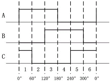
[0028] 1. Define the interval number i of the three-phase Hall position signal and the initial angle value of the interval, such as figure 1 As shown, set the ABC three-phase Hall signal to be 1 when the level is high, and to be 0 when the level is low.

[0029] ABC=101: i=1, interval initial angle value: 0°

[0030] ABC=100: i=2, interval initial angle value: 60°

[0031] ABC=110: i=3, interval initial angle value: 120°

[0032] ABC=010: i=4, interval initial angle value: 180°

[0033] ABC=011: i=5, interval initial angle value: 240°

[0034] ABC=001: i=6, interval initial angle value: 300°

[0035]2. Drive the open-loop permanent magnet synchronous motor to run at a fixed speed with a VVVF constant voltage-frequency r...


PUM


Abstract

The invention relates to a three-phase sinusoidal voltage control driving system for a permanent magnet synchronous motor, in particular to a Hall position sensor-based position estimation and compensation method for the permanent magnet synchronous motor. The method comprises the following steps of: driving the permanent magnet synchronous motor to rotate at constant speed in a VVVF manner by a controller, and detecting a position signal transmitted back by a Hall sensor to obtain the distribution proportion of six position intervals under an electrical angle of 360 degrees; obtaining a position interval with a calculation number i according to the distribution proportion, and estimating a correction coefficient V[i] of an angle change value; and correcting T in an angle estimation formula 60*t / T to finally obtain a corrected angle estimation formula 60*t / (V[i]*T), wherein i is the number of the position interval, and V[i]*T in the corrected angle estimation formula is time actually required by the rotation of the motor by the position interval with the number i. A position angle change value calculated according to the formula in the interval always changes linearly within 0 to 60 degrees regardless of an electrical angle actually corresponding to the position interval.

Description

technical field [0001] The invention relates to a three-phase sinusoidal voltage control drive system of a permanent magnet synchronous motor, in particular to a method for estimating and compensating the position of the permanent magnet synchronous motor based on a Hall position sensor. Background technique [0002] With the development of motor technology, the application range of permanent magnet synchronous motors is becoming wider and wider. Due to its low power consumption and low noise characteristics, permanent magnet synchronous motors are used in various household appliances to replace previous induction motors, such as refrigerators, air conditioner compressors, blowers, etc. In addition, most of the latest electric vehicles also use permanent magnet synchronous motors. A high-power permanent magnet synchronous motor is used as its driving motor. [0003] The permanent magnet synchronous motor is a three-phase AC motor in which the rotor is a permanent magnet and...

Claims


Application Information

Patent Timeline
Patent Type & Authority Applications(China)
IPC IPC(8): H02P6/10
Inventor 贺骥蒲晓珉桂仲成金之铂徐立强李永龙肖唐杰
Owner DONGFANG ELECTRIC CORP LTD
Why Eureka
Try Eureka