Centralized control fire-fighting emergency lighting and evacuation indication system and implementing method thereof

An emergency lighting and fire emergency technology, which is applied in the field of centralized control fire emergency lighting evacuation indication system, can solve the problems of lagging maintenance and overhaul of emergency sign lights, system transmission speed bottleneck, and many evacuation exits, etc., to eliminate the blind area of ​​escape evacuation indication , Improve building safety factor, improve the effect of safety factor

Inactive Publication Date: 2013-01-16
合肥联信电源有限公司
View PDF3 Cites 12 Cited by
  • Summary
  • Abstract
  • Description
  • Claims
  • Application Information

AI Technical Summary

Problems solved by technology

[0005] 1. The current emergency sign lights exist as a single unit in the building, which cannot respond to changes in the fire scene, let alone dynamically adjust the escape direction indication, which brings difficulties to the scene escape
[0006] 2. There is a serious hysteresis phenomenon in the daily maintenance and repair of the emergency sign light. The main function of the emergency sign light is to start the emergency in case of fire, and the key to start the emergency is whether the battery charging and discharging work is normal
Relying on human maintenance and repair, product problems cannot be found in time
[0007] 3. In the event of a fire, it often brings many blind spots to the escape and evacuation instructions of the b

Method used


Image

  • Centralized control fire-fighting emergency lighting and evacuation indication system and implementing method thereof

Examples


Example Embodiment

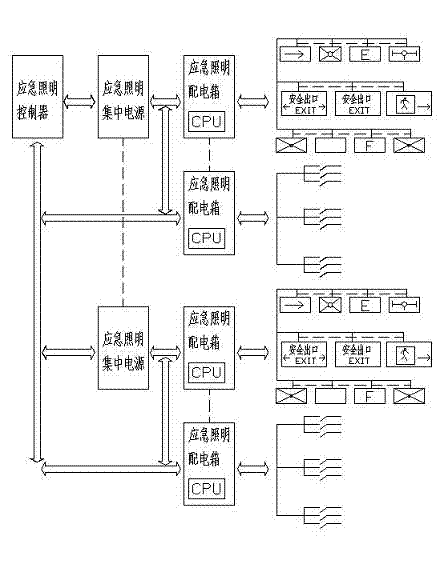
[0046] see figure 1 , Centralized control fire emergency lighting evacuation instruction system, composed of emergency lighting controller, centralized power supply for emergency lighting, distribution box for emergency lighting and emergency lamps with centralized power supply.

[0047] The emergency lighting controller controls 10 to 20 emergency lighting centralized power supplies, and the emergency lighting controller and the emergency lighting centralized power supply adopt a bus system connection mode.

[0048] The emergency lighting centralized power supply is connected to the emergency lighting distribution box according to the actual power.

[0049] The emergency lighting distribution box is connected to 20-30 emergency lamps or branches of emergency lamps.

[0050] The emergency lighting controller directly and remotely controls each lamp or each lamp, and displays the working status of each lamp or branch, as well as fault alarm and fault silencer, which is conveni...


PUM


Abstract

The invention relates to the field of of a fire-fighting emergency lighting and evacuation indication system of a modern intelligent building and particularly relates to a centralized control fire-fighting emergency lighting and evacuation indication system and an implementing method thereof. The centralized control fire-fighting emergency lighting and evacuation indication system consists of an emergency lighting controller, an emergency lighting centralized power supply, an emergency lighting power distribution box and a centralized power supply emergency lamp. By a network of the centralized control fire-fighting emergency lighting and evacuation indication system architecture with the centralized power supply, in the case of a fault, bottom layer equipment reports the fault to a host in a main reporting mode, a report is displayed on a software operation interface, the audible and visual alarm is simultaneously carried out to remind monitoring personnel and the routing inspection is uninterruptedly carried out in 24 hours; great manpower and material resources are saved; the difficult problem of daily maintenance and overhauling of a conventional emergency marker lamp is solved; the safety coefficient of the building is improved; and the centralized control fire-fighting emergency lighting and evacuation indication system has a fault routing inspection function of the bottom layer equipment. The regulation on the optimal escaping route when a fire occurs is implemented. The system is linked with a fire-fighting alarm system to carry out operations of control, command sending, stroboflash implementation, indication of emergency exits and the like on the bottom layer equipment.

Description

[0001] technical field [0002] The invention relates to the field of fire emergency lighting and evacuation indication system of modern intelligent buildings, in particular to a centralized control type fire emergency lighting evacuation indication system and its realization method. Background technique [0003] With the rapid economic development. The scale of domestic single buildings is getting bigger and bigger, not only in terms of height, but also constantly creating new heights. There is also an astonishing increase in single-layer area. increase in single-layer area. For fire evacuation, how to make escape safer, more accurate and faster when a fire occurs is a new topic proposed by the times for building disaster prevention. Centralized power supply and centralized control intelligent fire emergency lighting evacuation instruction and escape system overcomes this problem, and its introduction and implementation have been widely welcomed and praised by the constr...

Claims


Application Information

Patent Timeline
IPC IPC(8): H05B37/02
Inventor 李多山刘晖
Owner 合肥联信电源有限公司
Why Eureka
Try Eureka