Shaftless screw conveyor

A shaftless screw conveying and shaftless screw technology, applied in the field of shaftless screw conveyors, can solve the problems of unreasonable force, deformation and fracture, easy jamming, etc. Effect

Inactive Publication Date: 2013-01-23
ANHUI YITONG MACHINERY
View PDF8 Cites 4 Cited by
  • Summary
  • Abstract
  • Description
  • Claims
  • Application Information

AI Technical Summary

Problems solved by technology

[0004] The driving motor of the existing shaftless screw conveyor is generally located at the machine head, and is connected to the head end of the shaftless screw body through a reducer, so that the shaftless screw body is in a compressed state during operation. Due to unreasonable force, it is very difficult to Easy to get stuck or damaged or even deformed and broken

Method used


Image

  • Shaftless screw conveyor
  • Shaftless screw conveyor
  • Shaftless screw conveyor

Examples


Embodiment Construction

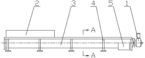
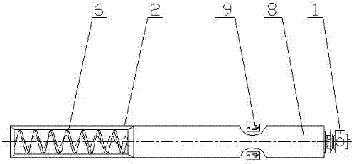
[0022] The shaftless screw conveyor consists of a driving device 1, a head assembly, a casing 3, a shaftless screw body 6, a tank liner 7, an inlet 2, an outlet 5, a cover 8, and a base.

[0023] exist figure 1 Among them, the driving device 1 is arranged at the end of the discharge port, and the driving device is connected with the tail end of the shaftless helical body, so that the shaftless helical body 6 is in a tensioned state during operation. The driving device 1 includes a motor and a reducer, and the reducer adopts a cycloidal pin wheel reducer or a shaft-mounted hardened gear reducer.

[0024] The head assembly is equipped with a thrust bearing, which can withstand the axial force generated when conveying materials.

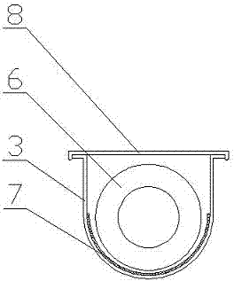
[0025] exist image 3 Among them, the casing 3 is U-shaped and made of stainless steel, carbon steel or glass fiber reinforced plastic. The top of the casing 3 is provided with a rainproof type cover 8 .

[0026] The shaftless spiral body 6 is made ...


PUM


Abstract

The invention discloses a shaftless screw conveyor. The shaftless screw conveyor comprises a driving device, a head assembly, an enclosure, a shaftless screw body, a trough body lining plate, a feeding port, a discharging port, a machine cover and a base, wherein the driving device is arranged at the discharging port end and comprises a motor and a speed reducer, the motor is connected with the speed reducer, the speed reducer is connected with the head end of the shaftless screw body, the head assembly is provided with a thrust bearing, the trough body lining plate is a wear-resistant plastic plate, a rubber plate or a glass-ceramic plate, the enclosure is U-shaped or O-shaped and is made of stainless steel, carbon steel or glass fiber reinforced plastic, the upper part of the enclosure is provided with the machine cover, the shaftless screw body is made of stainless steel or carbon steel, the feeding port and the discharging port are square or circular, and the base is connected with the enclosure through a support. The shaftless screw conveyor is compact in structure, reasonable in stress, smooth in material conveying without a bearing in a trough, and simple and convenient in maintenance; and except for the open feeding port and the discharging port, rest parts can all be closed by additionally arranging covers, so that materials cannot overflow and the pollution is reduced.

Description

[0001] technical field [0002] The invention relates to material conveying machinery, in particular to a shaftless screw conveyor. Background technique [0003] Compared with the traditional shafted screw conveyor, the shaftless screw conveyor adopts the design without a central shaft and uses a flexible integral steel screw to push materials, so it has the outstanding characteristics of strong anti-winding and no interference from the central shaft. It can convey materials that traditional shaft screw conveyors and belt conveyors cannot or are not easy to convey, such as granular and powdery materials, wet and pasty materials, semi-fluid and viscous materials, easily entangled and easily clogged materials. [0004] The driving motor of the existing shaftless screw conveyor is generally located at the machine head, and is connected to the head end of the shaftless screw body through a reducer, so that the shaftless screw body is in a compressed state during operation. Due t...

Claims


Application Information

Patent Timeline
Patent Type & Authority Applications(China)
IPC IPC(8): B65G33/14B65G33/24B65G33/26
Inventor 叶刚
Owner ANHUI YITONG MACHINERY
Why Eureka
Try Eureka