
Hydraulic gadder and oil distribution sliding valve thereof

A technology for hydraulic rock drills and oil slide valves, which is applied to mechanical equipment, fluid pressure actuators, servo motor components, etc., and can solve the problems of easy jamming of the valve core 12, heat generation of the valve core 12, and easy cracking of the right end surface of the valve core 12, etc. problem, to prolong the service life

Inactive Publication Date: 2015-05-20
深圳市普隆重工有限公司
View PDF6 Cites 0 Cited by
  • Summary
  • Abstract
  • Description
  • Claims
  • Application Information

AI Technical Summary

Problems solved by technology

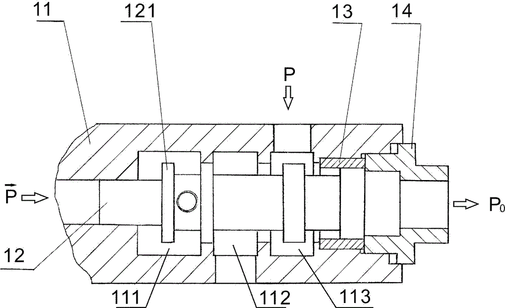
Due to structural design limitations, the contact area at the collision is not large. If the hardness of the valve core 12 is too high, the right end surface of the valve core 12 is easy to crack; if the hardness of the valve core 12 is low, the right end of the valve core 12 is easy to be upset. Deformation, the spool 12 is easy to jam, and the spool 12 heats up here seriously, which is the disadvantage of rigid positioning

Method used


Image

  • Hydraulic gadder and oil distribution sliding valve thereof
  • Hydraulic gadder and oil distribution sliding valve thereof
  • Hydraulic gadder and oil distribution sliding valve thereof

Examples


Embodiment 1

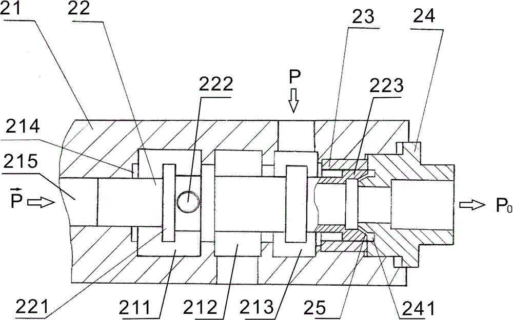
[0026] Please refer to figure 2 , an oil distribution slide valve of a hydraulic rock drill according to the present invention, comprising a valve body 21, a valve core 22, a valve sleeve 23 and a valve seat 24; the valve body 21 includes a signal input port 215, a low pressure chamber 211, an alternating chamber 212 and a normal pressure chamber 213, wherein the normal pressure chamber 213 communicates with the external hydraulic oil passage, the alternating chamber 212 communicates with the piston back chamber, and the low pressure chamber 211 communicates with the oil return passage; The left end of 22 is located in the signal input port 215, and there is a small gap between the hole wall of the signal input port 215, and the right end of the valve core 22 passes through the low-pressure chamber 211, the alternating chamber 212 and the normal-pressure chamber 213 successively, and then meets the valve seat. 24, the valve seat 24 is installed at one end of the valve body 21...

Embodiment 2

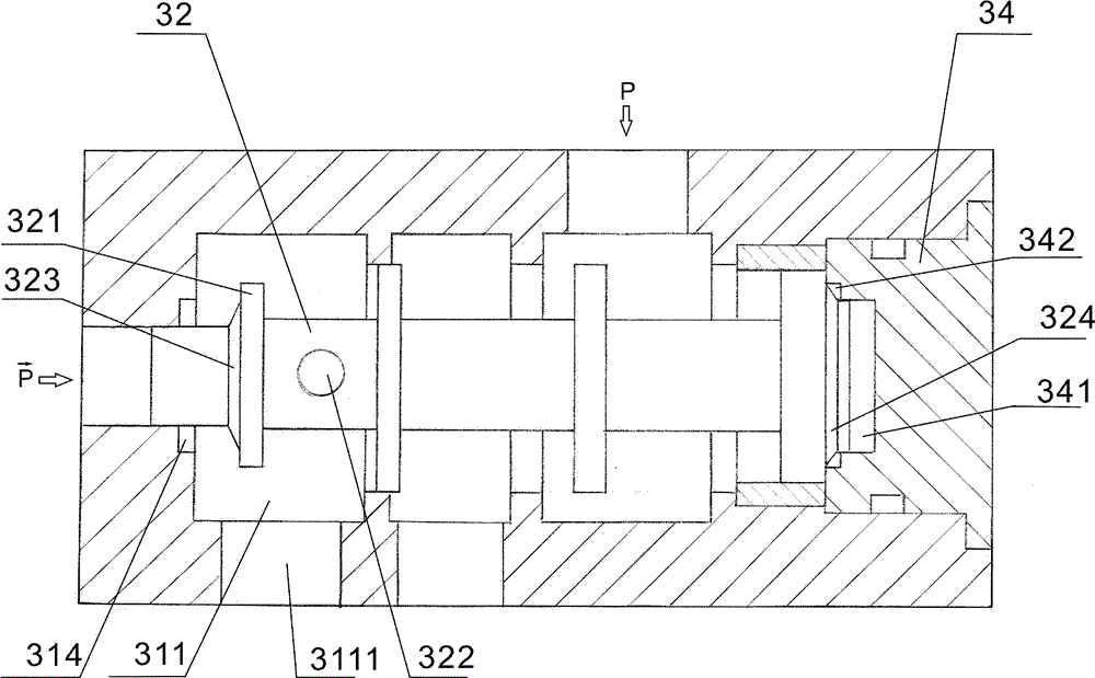
[0036] Please refer to image 3 and Figure 4 , the second embodiment of the oil distribution slide valve of a hydraulic rock drilling machine of the present invention is basically the same as the first embodiment in the working principle, basic structure, and deceleration principle of the oil distribution slide valve.

[0037] The difference of this example from Example 1 lies in the replacement of local structures, including:

[0038] The low-pressure chamber 311 communicates with the oil return passage through the channel 3111. The middle part of the valve seat 34 is provided with a stepped hole, and the part of the valve core 32 located in the low-pressure chamber 311 is provided with a round hole 322. 34 connected. The shape of the first buffer chamber 314 is the same as that of the first embodiment, and its size is slightly smaller than the shoulder boss 321 of the valve core 32. The shoulder boss 321 is provided with a conical surface 323 matching the first buffer cha...


PUM


Abstract

The invention relates to an oil distribution sliding valve for a hydraulic gadder. The oil distribution sliding valve comprises a valve body, a valve core and a valve seat, wherein the valve body comprises a signal input port, a low-pressure cavity, an alternating cavity and a normal pressure cavity; the cavities are communicated with corresponding holes; the left end of the valve core is arranged into the signal input port, and the right end of the valve core sequentially penetrates through the low-pressure cavity, the alternating cavity and the normal pressure cavity and is matched with the valve seat at the right end of the valve body; and the valve core controls open and close states of the holes through axial movement. The valve body also comprises a first buffering cavity and a second buffering cavity which are respectively formed in the cavity wall of the low-pressure cavity and the end face of the valve seat and are communicated with the low-pressure cavity; a left reversing extreme position and a right reversing extreme position are respectively arranged on a moving trace of the valve core; and the valve core is sealed at the left reversing extreme position and the right reversing extreme position respectively and compresses the first buffering cavity and the second buffering cavity. By the technical scheme, rigid collision in the oil distribution sliding valve can be eliminated; loss of structural members is reduced; and an opening of the valve core can be accurately positioned.

Description

technical field [0001] The invention relates to the field of rock drilling machines, in particular to a hydraulic rock drilling machine and an oil distribution slide valve thereof. Background technique [0002] In the hydraulic transmission system, the oil distribution slide valve is used to accurately input the liquid pressure flow into the actuator according to the designed direction, flow rate and pressure, which plays a very important role in the frequency response of the hydraulic system. In the existing hydraulic control system, especially in the process of low-frequency transposition oil distribution, the control movement of the slide valve has been very mature. However, the frequency of oil distribution and displacement control of hydraulic rock drills is relatively high (f≥40HZ), and the pressure oil that drives the actuator is used as the receiving signal of the oil distribution slide valve. Generally, the pressure is higher than 10MPa, so the oil distribution move...

Claims


Application Information

Patent Timeline
Patent Type & Authority Patents(China)
IPC IPC(8): F15B13/02
Inventor 王造时
Owner 深圳市普隆重工有限公司
Learn More