Impact tension testing apparatus

A technology of tensile test and pulse generating device, which is applied in the direction of measuring devices, instruments, scientific instruments, etc., can solve problems such as manufacturing difficulties, and achieve the effects of low structural sealing requirements, high success rate, and large gas output

Inactive Publication Date: 2013-01-23
HARBIN ENG UNIV
View PDF4 Cites 11 Cited by
  • Summary
  • Abstract
  • Description
  • Claims
  • Application Information

AI Technical Summary

Problems solved by technology

The disadvantage of this device is that the sealing requirements for the air chamber and the air circuit are relatively strict, so it is more difficult to manufacture.

Method used


Image

  • Impact tension testing apparatus
  • Impact tension testing apparatus
  • Impact tension testing apparatus

Examples


Embodiment Construction

[0026] The present invention is described in more detail below in conjunction with accompanying drawing example:

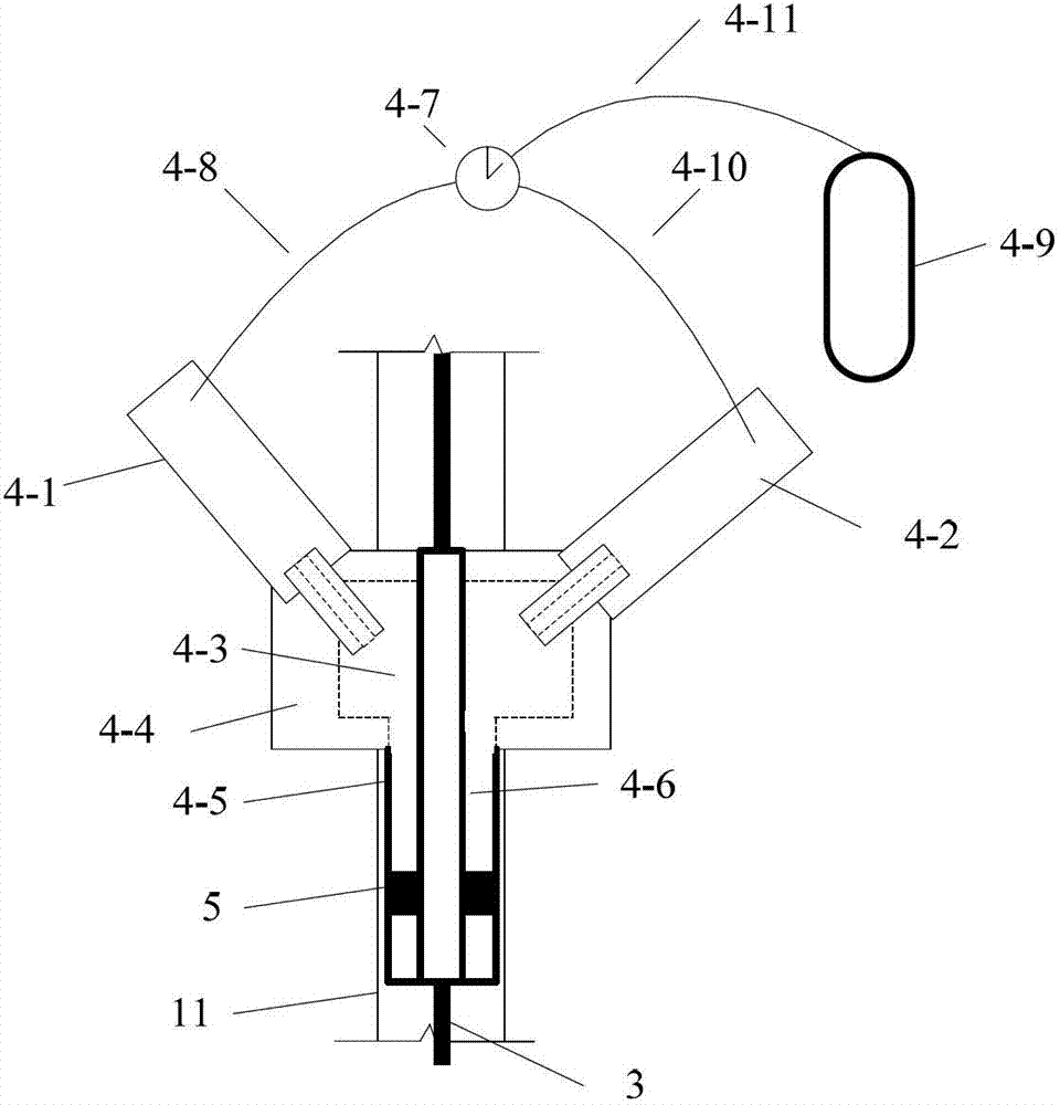
[0027] combine Figure 1-10 , the present invention is composed of a support base 11, a transmission rod 1, a test piece 2, an incident rod 3, a power generator 4, an annular collision block 5, a signal trigger device 7, a time interval meter 8, an absorption device 10, a strain gauge 12, a strain gauge Sheet 13, ultra-dynamic strain gauge 14, dynamic signal storage device 15, concrete base 6, and pulse generating device 9. It is characterized in that the transmission rod 1 is located on the left side of the base 11, the right end of the transmission rod 1 is connected to the left end of the test piece 2, the strain gauge 12 is pasted on the middle part of the transmission rod 1, and is connected with the ultra-dynamic strain gauge 14 through a wire, and the test piece 2. The right end is connected to the left end of the incident rod 3. The incident rod 3 is loca...


PUM


Abstract

The invention aims at providing an impact tension testing apparatus which comprises a supporting pedestal, a concrete pedestal, a transmitting rod, an incident rod, strain gauges, a strain indicator, a dynamic signal memory, a power generator, an annular collision block, a signal triggering device, a time interval instrument, a pulse generating device and an absorbing device; the transmitting rod, the incident rod and the power generator are arranged on the supporting pedestal; a detected test piece is arranged between the transmitting rod and the incident rod which are respectively stuck with the strain gauges; the strain gauges are connected with the strain indicator through lead wires; the incident rod sequentially penetrates through the power generator, the signal triggering device and the time interval instrument and is connected with the power generating device; the pulse generating device is arranged in the absorbing device which is arranged on the concrete pedestal; the signal triggering device is connected with the dynamic signal memory; the strain indicator is connected with the dynamic signal memory; and the annular collision block is arranged in the power generator. The impact tension testing apparatus is simply structured, convenient to mount and remarkably advantaged in cost.

Description

technical field [0001] The invention relates to a test device for testing the dynamic tensile mechanical properties of materials. Background technique [0002] Explosion, high-speed impact, metal cutting, etc. are relatively common impact loads in engineering. This type of load is characterized by a short action time (generally in the order of microseconds or nanoseconds) and high impact strength (enough to cause material damage). The mechanical properties exhibited by materials under dynamic loading will be very different from those under static or quasi-static conditions. Therefore, it is of great engineering significance and academic value to study the mechanical properties of materials under impact loads. In order to simulate the impact loading process at various rates, the design of the test device becomes one of the key issues. The issue of dynamic tensile properties of materials is becoming a hot topic of discussion and research, but this kind of test device is stil...

Claims


Application Information

Patent Timeline
Patent Type & Authority Applications(China)
IPC IPC(8): G01N3/307
Inventor 邹广平唱忠良李雨蕾孙杭其
Owner HARBIN ENG UNIV
Why Eureka
Try Eureka