Unlock instant, AI-driven research and patent intelligence for your innovation.

A reactive power measurement method and device for improving reactive power error

A technology of power measurement and error, applied in the field of reactive power measurement method and device for improving reactive power error, can solve problems such as unqualified error, large error, incorrect reactive power, etc., achieve normal reactive power error, improve reactive power The effect of power error

Active Publication Date: 2016-02-24
ZHANGZHOU CANNET ELECTRICAL APPLIANCE
View PDF5 Cites 0 Cited by
  • Summary
  • Abstract
  • Description
  • Claims
  • Application Information

AI Technical Summary

Problems solved by technology

[0004] As a dedicated analog / digital conversion chip, the metering chip CS5463 integrates a power grid frequency measurement unit inside, and the measurement accuracy is also very high, which can reach 0.00001 seconds, but its frequency value update speed is fixed at 10 seconds when the chip leaves the factory, while the metering chip The reactive power metering function of CS5463 requires accurate and real-time power grid frequency for normal metering
[0005] When doing the frequency impact test, it is necessary to measure the reactive power error value of each frequency point. After switching from one frequency point to another frequency point, the grid frequency has been updated, but the frequency cycle measured inside the metering chip has not yet arrived, and the value before switching is still used. Frequency, at this time the measured reactive power is not correct, and there will be several large errors in the reaction of the reactive power error, and the measured error is unqualified

Method used


Image

  • A reactive power measurement method and device for improving reactive power error
  • A reactive power measurement method and device for improving reactive power error

Examples


Embodiment

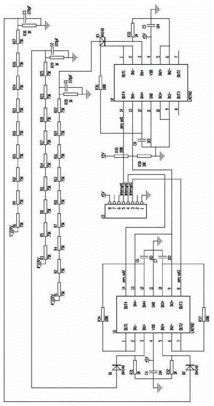
[0039] In this embodiment, the implementation of the method of the present invention requires three interrupt ports and a timer with a period of 1 millisecond to measure the three-phase grid frequency. Measure the frequency of phase A when the voltage of phase A is greater than 135V, otherwise measure the frequency of phase B if the voltage of phase B is greater than 135V, otherwise measure the frequency of phase C if the voltage of phase C is greater than 135V, and do not measure the frequency if the voltage of all three phases is lower than 135V. The default grid frequency is 50Hz. Generally, the grid frequency of the three-phase input of the ammeter is consistent, and only one phase can be measured. When the voltage is lower than 135V, that is, 60% of 220V, the measured frequency may not be accurate, so try to test the voltage of other phases.

[0040] In this embodiment, the operational amplifier is LM2902, that is, the peripheral circuit is composed of a diode and an int...


PUM


Abstract

The invention relates to a reactive power measurement method and device capable of improving a reactive power error. The method comprises the following steps: 1) inputting a voltage signal into an operation amplifier through a diode, and outputting a zero crossing signal; 2) connecting the output end of the operation amplifier with an interruption pin of a single chip micro-computer; 3) measuring a time interval between two interruption signals by a timer of the single chip micro-computer; 4) taking a reciprocal of the time interval acquired in step 3) so as to acquire a power frequency; and 5) outputting the power frequency to a measurement chip so as to measure the reactive power. According to the invention, the timer of the single chip micro-computer is used for measuring the power frequency to obtain the real-time power frequency, so that the frequency affected reactive power error can be improved. With the method, the power frequency can be timely updated during the reactive frequency affected switching, and the reactive power error is normal.

Description

technical field [0001] The invention relates to the field of power grid monitoring, and more specifically relates to a reactive power measurement method and device for improving reactive power errors. Background technique [0002] Chinese utility model patent ZL200320123064.8 relates to a reactive power measurement circuit used in an all-electronic watt-hour meter to realize a ninety-degree phase shift, including: an analog / digital conversion circuit for receiving current channel signals, a down-sampling circuit, Low-pass filter circuit; analog / digital conversion circuit and phase compensation circuit for receiving voltage channel signals; digital multiplier, low-pass filter circuit, and digital / frequency conversion circuit for receiving signals from the low-pass filter circuit and phase compensation circuit respectively; its characteristics It is: a differential unit circuit capable of 90° phase shift is arranged between the down-sampling circuit and the low-pass filter cir...

Claims


Application Information

Patent Timeline
Patent Type & Authority Patents(China)
IPC IPC(8): G01R11/52
Inventor 陈宝盛曾戈弋许来顺许惠峰
Owner ZHANGZHOU CANNET ELECTRICAL APPLIANCE