
Control device for power supply circuit

一种电力供应、控制装置的技术,应用在电池电路装置、电池/燃料电池控制装置、电路装置等方向,达到减小工作风险的效果

Active Publication Date: 2013-01-23
SUZUKI MOTOR CORP
View PDF4 Cites 5 Cited by
  • Summary
  • Abstract
  • Description
  • Claims
  • Application Information

AI Technical Summary

Problems solved by technology

The execution of the operation of breaking the safety switch will open (OPEN) the relay (main relay) and thus interrupt the high voltage circuit

Method used


Image

  • Control device for power supply circuit
  • Control device for power supply circuit
  • Control device for power supply circuit

Examples


Embodiment 1

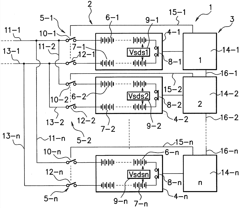
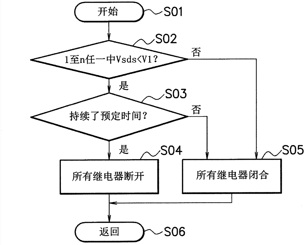
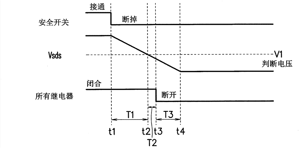
[0027] Figure 1 to Figure 3 Example 1 of the present invention is shown.

[0028] exist figure 1 In , reference numeral 1 denotes an electric propulsion unit installed in a vehicle such as an electric vehicle, a hybrid vehicle, or the like. In the electric propulsion unit 1, an electric power supply circuit 2 and an electronic control device 3 are provided.

[0029] The power supply circuit 2 is provided with a plurality of first to nth battery packs 4-1 to 4-n connected in parallel with each other as high-voltage battery packs, and is provided with a switch capable of disconnecting the first to nth battery packs 4-1 to 4-n. The first to nth relays (main relays) 5-1 to 5-n of the electric power supply.

[0030] The first battery pack 4-1 includes a plurality of first positive electrode side battery cells (unit cells) 6-1 connected in series with each other and a plurality of first positive electrode side battery cells 6-1 connected in series with each other and in paralle...

Embodiment 2

[0056] Figure 4 to Figure 6 Example 2 of the present invention is shown.

[0057] Embodiment 2 is described by using the same reference numerals for portions having the same functions as in Embodiment 1 described above.

[0058] The features of Embodiment 2 are as follows. Specifically, as Figure 4 As shown in , the structure is configured so that, in the judgment about the safety switch of a car in which a plurality of battery packs are mounted in parallel, when detection is made using a voltage change using a circuit existing in the total voltage of the battery, the relay (5 -1 to 5-n) Under the condition of disconnection (OPEN), compare the measured voltage Va (V) on the area a (corresponding to the resistor Ra) of the existing circuit with the total voltage Vb ( V) Calculated voltage Vba (V) on area a, and by the difference (D) between these two voltages occurring for a predetermined time (judgment time) (s) or more, to identify one of the plurality of safety switches...


PUM


Abstract

Provided is a control device for a power supply circuit in which a plurality of high-voltage battery packs are provided, wherein if any one safety switch is off, the startup state of a high-voltage circuit is totally prevented, even when a careless mistake such as a careless power-on operation is made, the circuit is prevented from being started, and also the overall power supply is cut off by turning off one safety switch, thereby improving the convenience of work. A voltage detection means (9-1 to 9-n) for detecting the internal voltage is provided in a battery pack (4-1 to 4-n), and by detecting the voltage change based on the operation of one or more safety switches (8-1 to 8-n), all relays (5-1 to 5-n) of a plurality of battery packs (4-1 to 4-n) provided in parallel are maintained in an open state.

Description

technical field [0001] The present invention relates to a control device for a power supply circuit, and more particularly to a control device for a power supply circuit for managing the power supply and power-off states of a power supply circuit provided in an electric propulsion unit mounted in a vehicle such as an electric car, a hybrid vehicle, etc. . Background technique [0002] In recent years, environmentally friendly vehicles such as hybrid vehicles, electric vehicles, and fuel cell vehicles have attracted attention. In such an environmentally friendly vehicle, a battery that supplies drive electric power to a drive motor is installed as a power source. [0003] In such a vehicle including a battery, as a means of maintaining the maximum output of the battery and prolonging the running distance when running only by electric power of the battery, mounting a plurality of batteries to increase the battery capacity has been studied. [0004] Generally, the battery is ...

Claims


Application Information

Patent Timeline
Patent Type & Authority Applications(China)
IPC IPC(8): H02J7/00B60L3/00H01M10/44H01M10/48H01M50/574
CPCH01M2220/20H01M10/482Y02E60/12Y02T10/7055B60L11/1864H02J7/0021B60L11/1803Y02T10/7005B60L3/04B60L3/0046B60L3/0069Y02T10/7061G01R31/3658B60L2240/547H01M10/4207B60L11/1853B60L2240/549G01R31/362H01M2010/4278H02J1/10H01M2/34H02H11/007B60L50/51B60L58/18B60L58/21G01R31/396G01R31/3835B60L58/20Y02T10/70Y02E60/10H02J7/0013H02J7/0048H01M50/574
Inventor 佐藤贤治铃木清子
Owner SUZUKI MOTOR CORP
Learn More