Staple bin assembly and stapler using same
A technology of components and staple cartridges, applied in the direction of surgical fixation nails, etc., can solve the problems of increased patient pain, poor staple formation, and continuous tissue cutting.
- Summary
- Abstract
- Description
- Claims
- Application Information
AI Technical Summary
Problems solved by technology
Method used
Image
Examples
Embodiment Construction
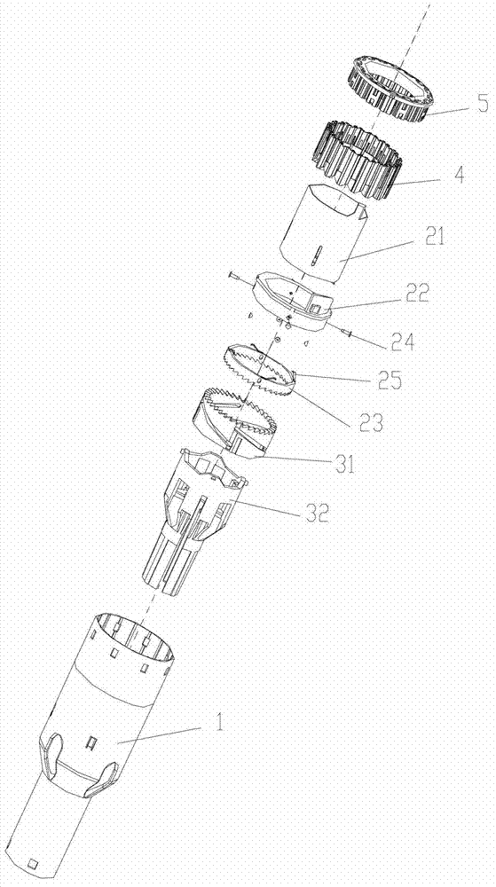
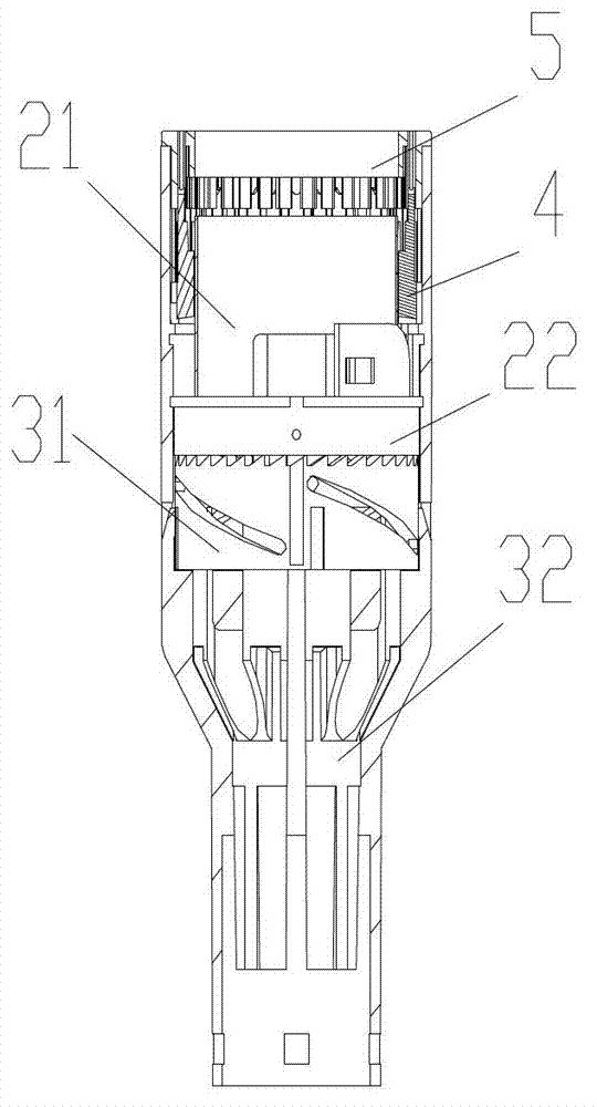
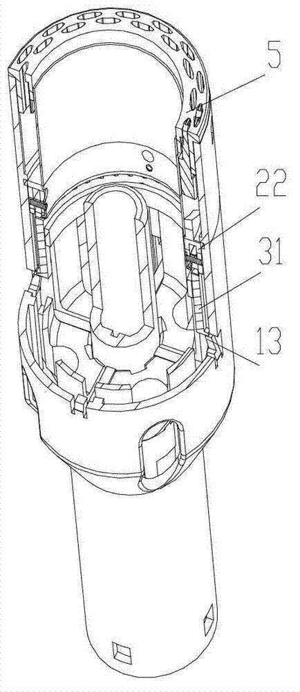
[0031] see Figure 1-3 As shown, a staple cartridge assembly of the present invention includes a staple cartridge cover 1, a staple cartridge 5 fixed on the upper end of the staple cartridge cover 1, a nail pusher 4 installed in the staple cartridge cover 1, a slit assembly and a driving assembly .
[0032] The following up, down, left and right are all based on figure 1 The orientation shown in is a standard description.
[0033] Among them, please refer to Figure 4 As shown, the kerf assembly includes a cutter slider 21 , a nail pusher slider 22 and a cutter gear ring 23 . The lower part of the cutter slider 21 is a cylinder, and the upper end is a cutting head 211. The push nail 4 and the push nail slider 22 can slide up and down and are set on the outside of the cylinder of the cutter slider 21. The push nail 4 is located on the push nail. Slider 22 above. The cutter gear ring 23 is installed on the bottom of the nail pushing slider 22 .
[0034] Please refer to F...
PUM
 Abstract
Description
Claims
Application Information
 - R&D
- Intellectual Property
- Life Sciences
- Materials
- Tech Scout
- Unparalleled Data Quality
- Higher Quality Content
- 60% Fewer Hallucinations
Browse by: Latest US Patents, China's latest patents, Technical Efficacy Thesaurus, Application Domain, Technology Topic, Popular Technical Reports.
© 2025 PatSnap. All rights reserved.Legal|Privacy policy|Modern Slavery Act Transparency Statement|Sitemap|About US| Contact US: help@patsnap.com


