Laser marking machine

A laser marking machine and laser technology, used in typewriters, printing and other directions, can solve the problems of difficult matching, high consumption, affecting work efficiency, etc., to save the waste of materials, waste of labor hours, and the rate of defective products. The effect of reducing and improving production efficiency

Active Publication Date: 2013-01-30
SUZHOU LOCUS TECH
View PDF7 Cites 5 Cited by
  • Summary
  • Abstract
  • Description
  • Claims
  • Application Information

AI Technical Summary

Problems solved by technology

[0002] At present, marking equipment generally uses the ink method, but the ink is easy to wipe off, and the processing speed of the ink printer is also very slow, which affects work efficiency
The conversion efficiency is low, the volume is large, and the consumption is large, which cannot guarantee the fineness of the marking effect and cannot be repeated. The operation of the machine is unstable, and the diameter of the output marking mark is large.
The working material range of the marking machine is small, and it is not easy to match with various production lines

Method used


Image

  • Laser marking machine
  • Laser marking machine
  • Laser marking machine

Examples


Embodiment Construction

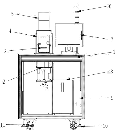
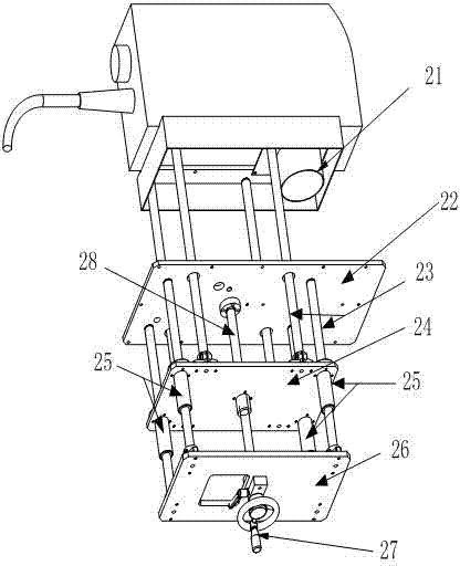
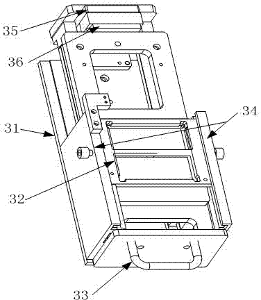
[0018] Such as figure 1 As shown, the laser marking machine includes a frame 1. The frame 1 is a cube made of profiles and a hollow workbench in the middle. A transmission device is fixed on one side of the workbench through a transmission fixing plate 22. The transmission device is based on the table surface of the workbench. It is divided into laser part 4 and transmission part 2. The laser part 4 is located above the table top, and the transmission part 2 is located below the worktable table and in the hollow of the workbench. The transmission part 2 cooperates with the laser part 4 through the transmission pair 28 , the top of the laser part 4 is provided with a laser head device 5, and the transmission fixing plate 22 of the transmission device is fixed with a sliding table mechanism 3, and the sliding table mechanism 3 is in the inside of the laser part 4, and the sliding table mechanism 3 and the laser head device 5 Cooperate with each other, the other side of the workb...


PUM


Abstract

The invention provides a laser marking machine, which comprises a rack, wherein the rack is a workbench; the workbench is a cube made of section bars; the middle of the workbench is hollow; one side of the workbench is fixedly provided with a transmission device by a transmission fixing board; the transmission device is divided into a laser component and a transmission part by the table board of the workbench; the laser component is positioned above the table board of the workbench; the transmission component is positioned below the table board of the workbench and is positioned in the hollow part of the workbench; the transmission component is cooperated with the laser component by a transmission pair; the top of the laser component is provided with a laser head device; the transmission fixing board of the transmission device is fixedly provided with a sliding table mechanism; the sliding table mechanism is positioned in the laser component; the sliding table mechanism is mutually cooperated with the laser head device; the other side of the workbench is provided with a PC (personal computer) display; and the PC display is provided with an indicating lamp device. The cooperation of a movable product placement table on the sliding table mechanism and the transmission pair in the transmission component can be controlled by a PC host to realize marking, so that the yield of the laser marking machine is improved, the laser marking machine is simple to operate, and the production efficiency is improved.

Description

technical field [0001] The invention relates to a laser marking machine, in particular to a laser marking device for semiconductor integrated silicon chips, which belongs to the technical field of mechanical and electronic industrial automation. Background technique [0002] At present, marking equipment generally uses the ink method, but the ink is easy to wipe off, and the processing speed of the ink printer is also very slow, which affects work efficiency. The conversion efficiency is low, the volume is large, and the consumption is large, which cannot guarantee the fineness of the marking effect and cannot be repeated. The operation of the machine is unstable, and the diameter of the output marking mark is large. The working material range of the marking machine is small, and it is not easy to match with various production lines. At present, the application of laser marking technology in the industry at home and abroad is being gradually paid attention to. Various new m...

Claims


Application Information

Patent Timeline
Patent Type & Authority Applications(China)
IPC IPC(8): B41J2/435B41J3/407
Inventor 张军叶勇
Owner SUZHOU LOCUS TECH
Why Eureka
Try Eureka