Sewing machine and control method of sewing machine

A technology of sewing machine and cloth feeding mechanism, which is applied in the direction of sewing machine control devices, sewing machine components, program-controlled sewing machines, etc.

Active Publication Date: 2013-01-30
BROTHER KOGYO KK
View PDF6 Cites 21 Cited by
  • Summary
  • Abstract
  • Description
  • Claims
  • Application Information

AI Technical Summary

Problems solved by technology

Therefore, conventional sewing machines cannot keep the driving of the main shaft and the driving of the cloth feeding mechanism in synchronization with changes in the rotational speed of the main shaft.

Method used


Image

  • Sewing machine and control method of sewing machine
  • Sewing machine and control method of sewing machine
  • Sewing machine and control method of sewing machine

Examples


Embodiment Construction

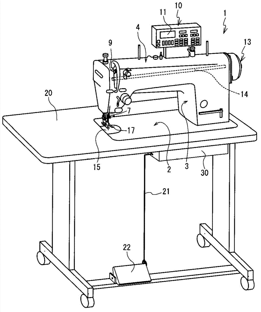
[0046] A first embodiment of the present invention will be described with reference to the drawings. figure 1 The upper side, the lower side, the right side, the left side, the front side, and the back side of the paper are the upper side, the lower side, the right side, the left side, the front side, and the rear side of the sewing machine 1, respectively.

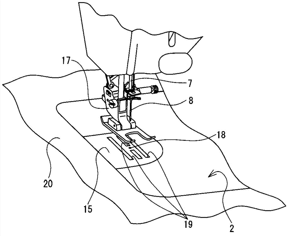
[0047] The sewing machine 1 has a base portion 2 , a pillar portion 3 , and an arm portion 4 . The machine base portion 2 is a base of the sewing machine 1 . The stand part 2 is attached to the recessed part (illustration omitted) of the upper surface of the table 20 from above. The pillar portion 3 extends vertically upward from the right end of the base portion 2 . The arm part 4 extends leftward from the upper end of the pillar part 3 and faces the upper surface of the stand part 2 . The machine arm 4 is provided with a presser foot 17 below the left end. The machine arm part 4 holds the needle bar 7 inside, and th...


PUM


Abstract

The invention relates to a sewing machine utilizes individual electric motors to drive a main shaft and a cloth delivery mechanism, and a control method of the sewing machine. The sewing machine has a main electric motor and a cloth delivery electric motor. The sewing machine drives the main shaft. The main shaft enables a sewing needle to move up and down. The cloth delivery electric motor drives the cloth delivery mechanism. A power transmission mechanism of the sewing machine converts each rotation movement toward a direct or opposite directions of an output shaft of the cloth delivery electric motor into swinging motion in which the cloth delivery mechanism goes back and forth horizontally and swing once, so that the power of the cloth delivery electric motor is transmitted to the cloth delivery mechanism. A CPU of the sewing machine detects a main rotation angle (S11). The main rotation angle is the rotation angle of the output shaft of the main electric motor. The CPU detects cloth delivery rotation angles (S13, S19). Each cloth delivery rotation angle is the rotation angle of the output shaft of the cloth delivery electric motor. The CPU calculates rotation speeds (S16, S22) indicated to the cloth delivery electric motor through the main rotation angle and the cloth delivery rotation angles.

Description

technical field [0001] The invention relates to a sewing machine and a control method of the sewing machine which use their respective motors to drive a main shaft and a cloth feeding mechanism. Background technique [0002] There is a sewing machine in which a main shaft and a cloth feeding mechanism are driven by separate motors. Since this sewing machine can freely control the cloth feed amount, various patterns can be easily sewn. In the sewing machine disclosed in Japanese Patent Laid-Open No. 92444 of 1979, cloth feed teeth are connected to the output shaft of the cloth feed motor. The cloth feeding motor is a stepping motor. If the cloth feed motor makes the output shaft reciprocate once within the specified angle range, the cloth feed teeth reciprocate once in the horizontal direction. [0003] When utilizing respective electric motors to drive the main shaft and the cloth feeding mechanism, the sewing machine needs to keep the driving of the main shaft and the dr...

Claims


Application Information

Patent Timeline
Patent Type & Authority Applications(China)
IPC IPC(8): D05B27/02D05B69/02D05B19/16
Inventor 加藤雅史竹村彻
Owner BROTHER KOGYO KK
Why Eureka
Try Eureka