
Construction method for performing pressure grouting in interlayer space

A technology of pressure grouting and construction method, which is applied in the direction of basic structure engineering and construction, which can solve the problems of grouting pipe blockage, poor potential energy, and difficulty in filling the grouting space, so as to reduce flow resistance, improve grouting efficiency, and ensure grouting quality effect

Active Publication Date: 2013-01-30
CHINA NUCLEAR IND 22ND CONSTR
View PDF3 Cites 0 Cited by
  • Summary
  • Abstract
  • Description
  • Claims
  • Application Information

AI Technical Summary

Problems solved by technology

[0008] Self-weight method: only rely on the grouting material's own gravity to flow within the grouting range. For a large amount of grouting at one time, a small grouting space and a long distance, it is difficult to fill the entire grouting space relying on its own fluidity
[0009] High-level funnel method: it relies on the potential energy difference of grouting to improve the fluidity of grouting. When the amount of grouting is large at one time and the structure of the grouting area is particularly complicated, it is difficult to ensure that the grouting material can fully fill all areas and corners
[0010] Pressure grouting method: It relies on grouting booster equipment to increase the pressure of grouting material for grouting. For a large amount of one-time grouting and a long grouting distance, the use of pressure grouting will easily cause blockage of the grouting pipe and make it impossible to continue grouting

Method used


Image

  • Construction method for performing pressure grouting in interlayer space
  • Construction method for performing pressure grouting in interlayer space
  • Construction method for performing pressure grouting in interlayer space

Examples


Embodiment approach

[0035] General implementation of the present invention is as follows:

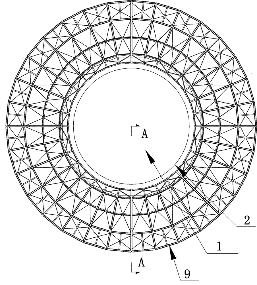
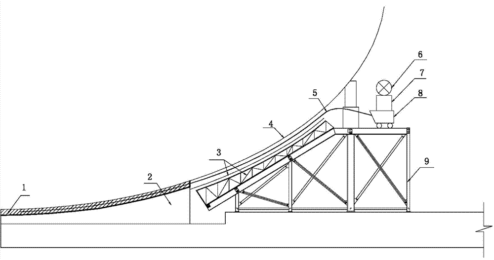
[0036] A construction method for pressure grouting in an interlayer space, comprising the following steps:

[0037] (1) Base treatment: Chisel the base, and the chisel direction is radial to form drainage grooves;

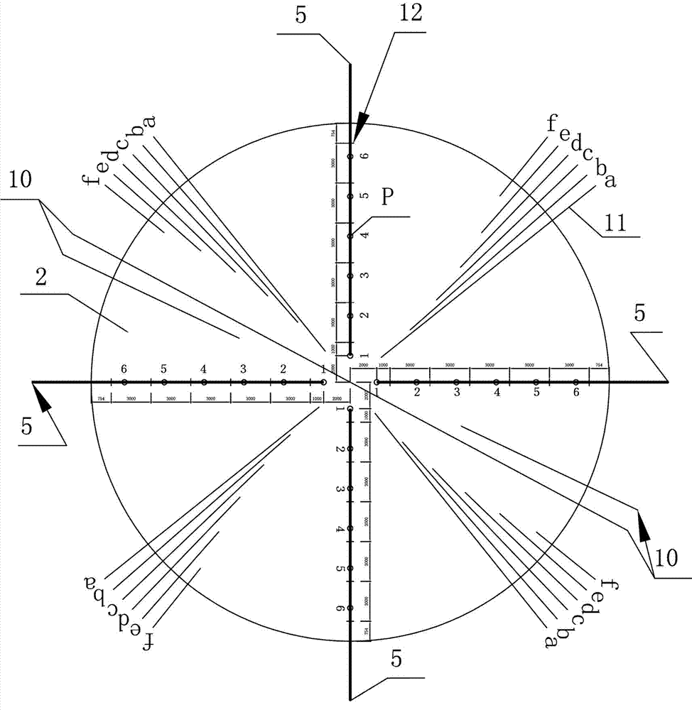
[0038] (2) Arrangement of grouting pipes, water suction pipes, and wires of liquid level monitors for liquid level monitors: evenly arrange multiple grouting pipes on the surface of the foundation after the roughening treatment, and the grouting pipes are fixed on the surface of the foundation by pipe clips; Multiple water suction pipes are arranged on the surface of the foundation; at the same time, multiple wires of liquid level monitors of different lengths are arranged between the grouting pipes;

[0039] (3) Place the grouting area to cover the overhead layer, and the space formed between the overhead layer and the base layer is the grouting area;

[0040] (4) Each grouting pipe is conne...


PUM


Abstract

A construction method for performing pressure grouting in an interlayer space mainly comprises the following steps of: treating the foundation course; distributing grouting pipes, a water absorption pipe and a liquid level monitor lead of a liquid level monitor: placing a grouting-region overhead space and taking a space between the overhead space and the foundation course as a grouting region; connecting each grouting pipe with a slurry making system; humidifying foundation course; lubricating the grouting pipes; grouting, and the like. The construction method for performing pressure grouting in the interlayer space is characterized in that the pipe lubrication operation is performed on the grouting pipes by means of a pipe lubricating material before the grouting, and a wet sliding layer is formed in the grouting pipes by means of a fine material in the pipe lubricating material, thereby reducing the flow resistance of grouting liquid in the grouting pipes, preventing the grouting material separation and the grouting pipe blockage and guaranteeing the smooth grouting operation; the pressure grouting is employed to ensure that the space of the whole grouting region is full of a grouting material; the liquid level monitor is matched with the grouting pipes and controls the grouting pipes to be located under the grouting liquid level all the time, so that the grouting pipes are controlled to accurately move to a specified grouting site; and therefore, the grouting quality is ensured and the grouting efficiency is improved.

Description

technical field [0001] The invention relates to a grouting construction method, in particular to a construction method for pressure grouting in an interlayer space. Background technique [0002] Grouting is a filling grouting process between the bottom surface of the bottom plate of the equipment or steel structure column foot and the surface of the concrete foundation to meet the requirements of close contact with the bottom plate and uniform load transfer. [0003] Existing grouting methods: [0004] Self-weight method: In the construction process of cement-based grouting materials, the grouting material has good flow properties and relies on its own gravity to flow by itself within the grouting range to meet the grouting requirements. [0005] High-level funnel method: When the fluidity of cement-based grouting materials alone cannot meet the grouting requirements during the construction of cement-based grouting materials, the high-level funnel is used to increase the po...

Claims


Application Information

Patent Timeline
IPC IPC(8): E02D15/02
Inventor 谢利平张斌余荆州许俊敏刘爱武
Owner CHINA NUCLEAR IND 22ND CONSTR
Learn More