Pneumatic valve and working method thereof

A gas direction and valve body technology, which is applied to valve operation/release devices, valve details, multi-port valves, etc., can solve the problems of complex structure, slow switching response speed and high manufacturing cost, and achieve low manufacturing cost and switching response. Fast, simple effects

Active Publication Date: 2013-01-30
大庆格瑞泰科技有限公司
View PDF6 Cites 5 Cited by
  • Summary
  • Abstract
  • Description
  • Claims
  • Application Information

AI Technical Summary

Problems solved by technology

However, the existing structure is complicated, the manufacturing cost is high, and the switching response speed is slow

Method used


Image

  • Pneumatic valve and working method thereof
  • Pneumatic valve and working method thereof
  • Pneumatic valve and working method thereof

Examples


Embodiment Construction

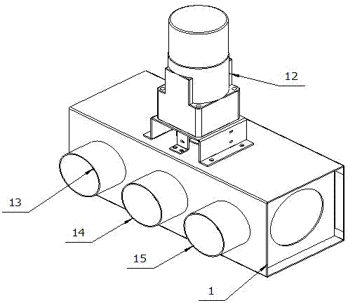
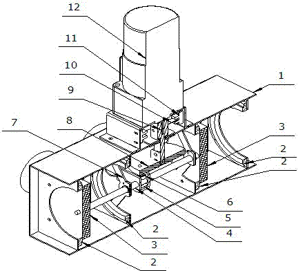
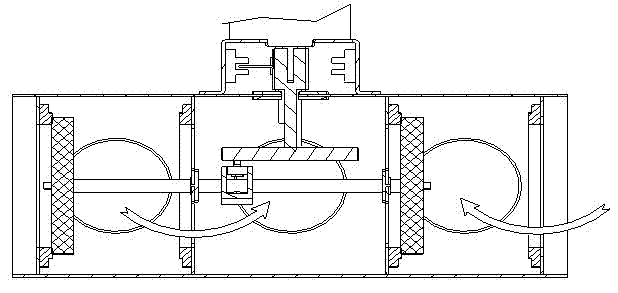
[0014] see figure 1 As shown in Figure 5, a pneumatic valve of the present invention includes a valve body 1, a motor 12 arranged above the valve body 1, a drive shaft 9 connected with the motor 12, and a drive shaft 9 connected with the drive shaft 9. 1. The cam 8 located in the valve body 1, the cam bearing 6 arranged under the cam 8, the cam bearing slideway 5 which is slidingly matched with the cam bearing 6, and the valve connecting rod shaft connected with the cam bearing slideway 5 4, and the valve plate 3 arranged at both ends of the valve plate connecting rod shaft 4; the valve body 1 is provided with four valve seats 2 that divide the valve body 1 evenly into three spaces, and two of the valve seats 2 are located on the valve body 1, the three spaces are sequentially connected with a fan suction interface 13, a transmission pipe interface 14 and a fan blowing interface 15.

[0015] Wherein, the end of the motor 12 close to the valve body 1 is provided with a photoel...


PUM


Abstract

The invention discloses a pneumatic valve and a working method thereof. The pneumatic valve comprises a valve body, a motor, a moving transmission shaft, a cam, a cam bearing, a cam bearing slideway, a valve plate connecting rod shaft and valve plates, wherein the motor is arranged above the valve body; the moving transmission shaft is connected with the motor; the cam is connected with the moving transmission shaft and positioned in the valve body; the cam bearing is arranged below the cam; the cam bearing slideway is in sliding fit with the cam bearing; the valve plate connecting rod shaft is connected with the cam bearing slideway; the valve plates are arranged on both ends of the valve plate connecting rod shaft; the valve body is internally provided with four valve seats which uniformly separate the valve body into three spaces, two of the valve seats are positioned on both ends of the valve body, and the three spaces are sequentially connected with a blower air draft interface, a transmission pipeline interface and a blower air blast interface. According to the invention, because the valve plates are driven by the motor to take straight-line motion in a left-right direction, the contact and sealing of the valve plates and the valve seats arranged among different positions are completed, and therefore the purpose of the switching of working states is finally achieved. The pneumatic valve disclosed by the invention has the advantages of simple structure, low manufacturing cost, fast switching response speed and stable and reliable operation.

Description

technical field [0001] The invention relates to an air direction valve and its working method. Background technique [0002] The gas direction valve is mainly used in the pneumatic pipeline transmission system, and is used to switch between the positive pressure (blowing), negative pressure (suction) and normal pressure of the pipeline in the pneumatic pipeline transmission system. However, the existing structure is complicated, the manufacturing cost is high, and the switching response speed is slow. Contents of the invention [0003] The main purpose of the present invention is to provide an air directional valve with simple structure, low manufacturing cost, fast switching response speed, stable and reliable operation. [0004] In order to solve the above problems, the present invention adopts the following technical solutions: an air-to-air valve, including a valve body, a motor arranged above the valve body, a drive shaft connected to the motor, and a drive shaft con...

Claims


Application Information

Patent Timeline
Patent Type & Authority Applications(China)
IPC IPC(8): F16K11/04F16K31/04F16K31/524B65G53/34
Inventor 王文龙
Owner 大庆格瑞泰科技有限公司
Why Eureka
Try Eureka