Double-wing type flow sensor

A flow sensor and double-wing technology, which is applied in the field of sensors, can solve the problems of low measurement accuracy, unstable outflow coefficient, and easy pollution accumulation, and achieve the effect of large measurement range, stable flow coefficient, and high measurement accuracy

Active Publication Date: 2015-03-25
南京新流道节能科技有限公司
View PDF5 Cites 0 Cited by
  • Summary
  • Abstract
  • Description
  • Claims
  • Application Information

AI Technical Summary

Problems solved by technology

Due to the advantages of simple structure, convenient assembly and disassembly, low cost, and small pressure loss, the equalizing tube is often used as the preferred instrument when it is only used for working condition monitoring without accurate measurement for trade accounting, especially in the case of large-diameter pipelines. However, its performance has serious defects, such as narrow measurement range, easy to accumulate dirt, large pressure loss, unstable outflow coefficient, etc.
Later, people invented some improved measuring devices based on orifice plates and nozzles (such as the V-Cone cone in the United States), but their sharp edges still cannot eliminate the edge wear caused by similar orifice plates and nozzles. Performance defects of unstable outflow coefficient and large pressure loss
Although the Venturi tube has no similar defects, its Achilles' heel lies in: the structure is not compact, the geometric profile is complicated, the manufacturing is difficult, and it is difficult to carry out precise processing, so the manufacturing cost is high, the measurement accuracy is low, and the adaptability to the use conditions is relatively small. Difference

Method used


Image

  • Double-wing type flow sensor
  • Double-wing type flow sensor
  • Double-wing type flow sensor

Examples


specific Embodiment approach 1

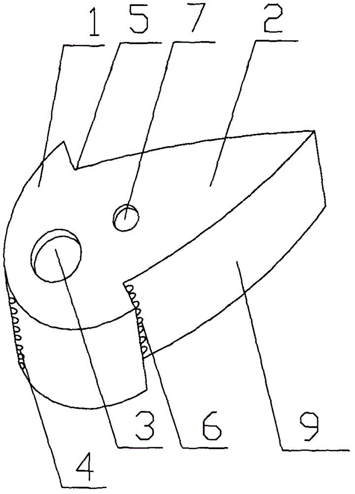
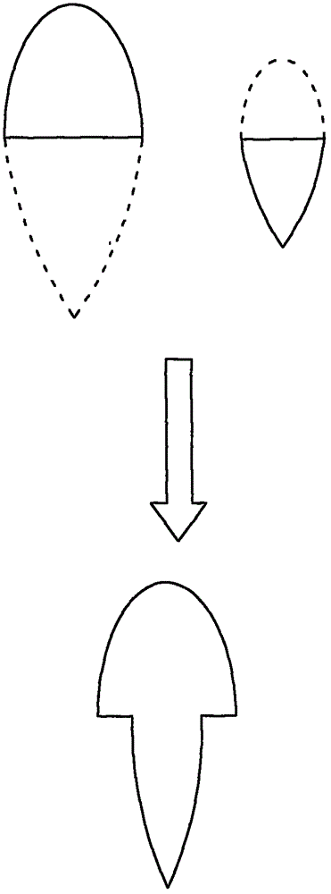
[0023] Specific implementation mode one: combine figure 1 , image 3 and Figure 4 To illustrate this embodiment, the double-wing flow sensor includes a flow sensor housing 9, the flow sensor housing 9 is composed of two large and small wings, the top of the large wing 1 is used as the head of the flow sensor, and the bottom of the small wing 2 As the tail of the flow sensor, a corner 5 is provided at the junction of the large and small wing shapes, so that the fluid flows and separates at the corner; the head 10 of the large wing shape 1 has a pressure tapping hole 4, and its end surface is provided with a high pressure Cavity 3, the high-pressure chamber 3 communicates with the pressure-taking hole 4; the end face of the small wing-shaped 2 is provided with a low-pressure chamber 7, which communicates with the row holes 6 or grooves at the corners of the large and small wing-shaped.

specific Embodiment approach 2

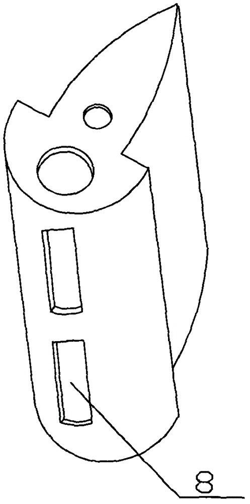
[0024] Specific implementation mode two: combination figure 2 To illustrate this embodiment, the difference between this embodiment and the double-wing flow sensor described in Embodiment 1 is that the head of the large wing is provided with a groove 8, and the groove 8 communicates with the high-pressure chamber 3 .

specific Embodiment approach 3

[0025] Specific implementation mode three: combination Figure 5 Describe this embodiment, the difference between this specific embodiment and the double-wing flow sensor described in the first or second specific embodiment is that the head 10 of the large wing shape is provided with an upstream passivation surface 12, and the large and small An additional wing 11 protruding outward is added to the corner of the junction of the two airfoils, so that the flow separation is more severe and the pressure drop is more obvious.


PUM


Abstract

The invention discloses a double-wing type flow sensor and a method for measuring flow by the sensor. The double-wing type flow sensor comprises a flow senor shell, and the flow sensor shell consists of a large wing and a small wing, the top of the large wing is used as the head of the flow sensor, the bottom of the small wing is used as the tail of the flow sensor, and a joint of the large wing and the small wing is provided with a corner so that fluid can separably flow at the corner. The head of the large swing is provided with a pressure hole or groove, a high-pressure cavity is reserved on an end face of the head of the large wing and communicated with the pressure hole or groove. A low-pressure cavity is reserved on an end face of the small wing and communicated with a discharge hole or groove at a corner of the large wing and the small wing. The double-wing type flow sensor can be disposed in a pipeline, the cross section of the flow sensor is formed by two sings, and by means of pressure difference of upstream high pressure and downstream low pressure generated when fluid to be tested flows through measuring pieces, the pressure difference can be converted into flow by a secondary device, and the flow can be displayed by a display device.

Description

technical field [0001] The invention relates to the technical field of sensors, in particular to a double-wing flow sensor and a method for measuring flow by using the sensor. Background technique [0002] If a measuring piece with a flow area smaller than the cross-sectional area of ​​the pipe is placed in a pipeline filled with fluid, the fluid bundle in the measuring pipeline will cause local contraction or flow separation when passing through the measuring piece. At the point of contraction or separation, the static pressure Will decrease, so there will be a certain pressure difference (also known as differential pressure) before and after the measuring piece. There is a certain functional relationship between the pressure difference and the flow rate, so the flow rate can be measured by measuring the pressure difference before and after the measuring piece placed in the pipeline. [0003] The existing flow sensors need to be placed in the pipeline, and the various flow...

Claims


Application Information

Patent Timeline
Patent Type & Authority Patents(China)
IPC IPC(8): G01F1/36
Inventor 明晓
Owner 南京新流道节能科技有限公司
Why Eureka
Try Eureka