Method and equipment for measuring laser line width

A laser line width and laser technology, which is applied in the direction of testing optical properties, can solve the problems of measuring line width, reducing the accuracy of line width measurement, and affecting the measurement results of line width.

Inactive Publication Date: 2013-01-30
NAT INST OF METROLOGY CHINA
View PDF6 Cites 22 Cited by
  • Summary
  • Abstract
  • Description
  • Claims
  • Application Information

AI Technical Summary

Problems solved by technology

[0019] However, for lasers with a wavelength that does not have a corresponding fiber amplifier, the linewidth cannot be measured by the loss-compensated time-delay self-heterodyne method
In addition, the line width broadening brought by the fiber amplifier, such as spontaneous emission, will reduce the accuracy of the line width measurement, and the phase noise brought by the fiber itself will also affect the line width measurement results

Method used


Image

  • Method and equipment for measuring laser line width
  • Method and equipment for measuring laser line width
  • Method and equipment for measuring laser line width

Examples


Embodiment Construction

[0047] In order to make the object, technical solution and advantages of the present invention clearer, the present invention will be described in further detail below in conjunction with specific embodiments and with reference to the accompanying drawings.

[0048] Figure 5 It is a flowchart of an embodiment of the laser line width measurement method of the present invention. Such as Figure 5 As shown, the flow process of the laser line width measurement method of this embodiment includes:

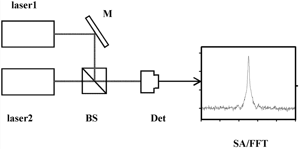
[0049] 101. Combine the first laser light output by the first laser and the second laser light output by the second laser. Wherein, the frequency of the first laser and the second laser are different and their phases are not correlated.

[0050] 102. Detect and receive the beat signal f after beam combining b , the beat signal f b Specifically, it is the difference frequency signal after the first laser beam and the second laser beam are combined and mixed.

[0051] 103, the beat ...


PUM


Abstract

The invention discloses a method and equipment for measuring laser line width. The method comprises the following steps of: combining a first laser output by a first laser device with a second laser output by a second laser device; dividing a combined beat note signal fb into a first beat note signal and a second beat note signal; mixing the first beat note signal fb and an ideal signal of which the frequency is f0 to obtain a difference frequency signal, namely the absolute value of fb-f0; due to a controllable bandwidth follow-up oscillator, generating a follow-up signal ft equal to the absolute value of fb-f0 under the follow-up bandwidth set by the follow-up oscillator; mixing the second beat note signal with the follow-up signal ft to output a difference frequency signal f0; and analyzing the difference frequency signal f0 to obtain the laser line width of the first laser device and/or the second laser device. Due to a circuit which is relatively simple, and by changing the servo bandwidth of the bandwidth-variable follow-up oscillator, the laser line width under a certain bandwidth of a narrow line width laser device and an ultra-narrow line width laser device can be measured.

Description

technical field [0001] The invention relates to laser line width measurement technology, in particular to a laser line width measurement method and equipment. Background technique [0002] Laser is widely used as a light source in various fields due to its characteristics of good monochromaticity, high brightness, strong directionality and strong coherence. The above characteristics of the laser can be attributed to its excellent narrow linewidth and good coherence compared with other light sources, so the output laser linewidth has become one of the important indicators for evaluating lasers. [0003] At present, the methods commonly used to measure the laser line width are as follows: [0004] (1) beat frequency measurement method [0005] Detect the beat frequency signals of the two lasers, and measure the linewidth of the beat frequency signals through a spectrum analyzer (spectrum analyzer, hereinafter referred to as: SA) or a dynamic signal analyzer (FFT), such as f...

Claims


Application Information

Patent Timeline
Patent Type & Authority Applications(China)
IPC IPC(8): G01M11/02
Inventor 臧二军赵阳曹建平李烨方占军
Owner NAT INST OF METROLOGY CHINA
Why Eureka
Try Eureka