Retroreflection coefficient measurement method adopting spectral correction

A retroreflection coefficient and spectral measurement technology, applied in the measurement of scattering characteristics, etc., can solve problems such as fitting degree and response characteristics, cost constraints, difficulty in perfection, deviation, etc., achieve optimal response characteristics and cost, and reduce system inconsistencies. Determining the degree component, improving the effect of accuracy and stability

Inactive Publication Date: 2013-01-30
RES INST OF HIGHWAY MINIST OF TRANSPORT +1
View PDF5 Cites 14 Cited by
  • Summary
  • Abstract
  • Description
  • Claims
  • Application Information

AI Technical Summary

Problems solved by technology

Among them, the test light source is affected by its own performance, power supply fluctuations, light decay, etc., and the spectrum of its emitted light has a certain deviation from the standard A light source spectrum; the photopic function correction device is obtained by combining and superimposing one or a series of optical lenses. The spectral response effect that conforms to the characteristics of the human eye is technically difficult to achieve a perfect fit for each wavelength, and there are mutual constraints between the degree of fitting, response characteristics, and cost

Method used


Image

  • Retroreflection coefficient measurement method adopting spectral correction
  • Retroreflection coefficient measurement method adopting spectral correction
  • Retroreflection coefficient measurement method adopting spectral correction

Examples


Embodiment 1

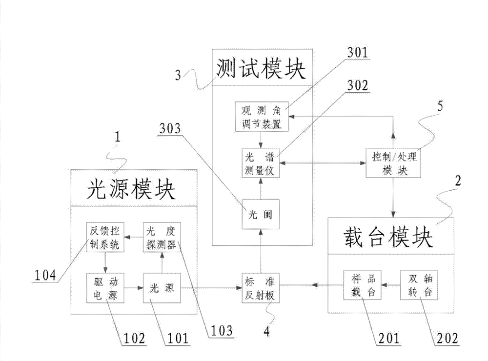
[0034] This embodiment provides a retroreflectance measuring device using spectral correction, see figure 1 , the device includes: a light source module 1, a stage module 2, a test module 3, a standard reflector 4 and a control / processing module 5, the light source module 1 is used to emit a stable visible spectrum, and the spectrum emitted by the light source module 1 is within the range of visible light The domestic requirements cover the spectral range to be studied and tested.

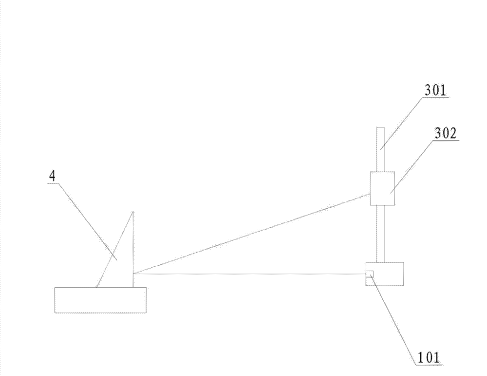
[0035] The light source module 1 and the carrier module 2 are arranged facing each other, the standard reflector 4 is arranged on the carrier module 2, the test module 3 and the light source module 1 are arranged on the same side of the carrier module 2, preferably, the test module 3 is arranged Above the light source module 1, and the angle of the carrier module 2 can be adjusted. In this way, the spectrum emitted by the light source module 1 can be irradiated flatly onto the standard reflector 4...

Embodiment 2

[0038] This embodiment provides a retroreflectance measuring device using spectral correction, see figure 1 with figure 2 , the device includes: a light source module 1, a stage module 2, a test module 3, a standard reflector 4 and a control / processing module 5, the light source module 1 is used to emit a stable visible spectrum, and the spectrum emitted by the light source module 1 is within the range of visible light The domestic requirements cover the spectral range to be studied and tested. The light source module 1 and the carrier module 2 are arranged facing each other, the standard reflector 4 is arranged on the carrier module 2, the test module 3 and the light source module 1 are arranged on the same side of the carrier module 2, preferably, the test module 3 is arranged Above the light source module 1, and the angle of the carrier module 2 can be adjusted. In this way, the spectrum emitted by the light source module 1 can be irradiated flatly onto the standard refl...

Embodiment 3

[0043] The present invention provides a method for measuring retroreflection coefficient using spectral correction, using the device provided by the above-mentioned embodiment, the measuring method includes:

[0044] S1, fix the standard reflector 4 on the sample carrier 201, turn on the measuring device, and adjust the geometric conditions of the optical path system to meet the assignment requirements of the standard reflector 4;

[0045] S2, under the condition that the light source 101 stably outputs the preset luminous intensity, obtain the relative radiation intensity spectral distribution of the reflected light of the standard reflector 4 through the test of the spectrometer 302;

[0046] S3, using software to correct the human eye photopic function V(λ) to obtain the relative luminous intensity spectral distribution of the reflected light of the standard reflector 4 at a certain geometric test angle;

[0047] Substitute the product of the preset output luminous intensit...


PUM


Abstract

The invention discloses a retroreflection coefficient measurement method adopting spectral correction. The retroreflection coefficient measurement method utilizes a retroreflection coefficient measurement device to realize measurement. The retroreflection coefficient measurement method comprises the following steps of adjusting the retroreflection coefficient measurement device, carrying out measurement by a spectral measurement instrument (302) to obtain relative radiation intensity spectral distribution of reflected light, correcting a human eye photopic vision function (lambda) by software to obtain relative radiation intensity spectral distribution of the reflected light at a certain geometric test angle, inputting a calibration coefficient of the spectral measurement instrument (302) into a control / processing module (5), putting a sample needing to be tested in an appointed position on a sample table (201), carrying out testing under different test geometric conditions, and carrying out correction by the calibration coefficient to obtain a retroreflection coefficient of the tested sample. The retroreflection coefficient measurement method utilizes a standard reflecting plate to realize spectral correction, greatly reduces an uncertainty component of a system, and improves accuracy and stability of measurement of a retroreflection coefficient of a retroreflection material.

Description

technical field [0001] The invention relates to the application field of road traffic engineering equipment, in particular to a method for measuring the retroreflection coefficient using spectral correction. The spectral calibration method reduces system uncertainty components and improves the measurement accuracy and stability of the retroreflective coefficient of retroreflective materials. . Background technique [0002] Retroreflective materials are widely used in the field of road traffic. It uses the lighting effect of the vehicle's own lights to transmit information such as instructions and warnings by controlling the angle range and intensity distribution of reflected light. Common products include retroreflective signs, raised road signs and signs. It is of great significance to ensure the safety of road transportation and improve the efficiency of traffic. [0003] The retroreflection coefficient measurement device adopts the optical path design and the angle contr...

Claims


Application Information

Patent Timeline
Patent Type & Authority Applications(China)
IPC IPC(8): G01N21/47
Inventor 杨勇朱传征韩文元张智勇朱立伟白媛媛李伟王峣王磊
Owner RES INST OF HIGHWAY MINIST OF TRANSPORT
Why Eureka
Try Eureka