Detection disc in metal detector

A technology of metal detectors and detection coils, which is applied in the field of metal detectors, can solve the problems of expanding production occupation space, affecting production efficiency, poor consistency of detection coils, etc., and achieves the effect of good batch production consistency and pollution prevention

Inactive Publication Date: 2013-01-30
SHANGHAI 21ST CENTURY ELECTRONICS EQUIP
View PDF7 Cites 0 Cited by
  • Summary
  • Abstract
  • Description
  • Claims
  • Application Information

AI Technical Summary

Problems solved by technology

[0003] The transmitting coil and receiving coil are distributed in the detection coil. The detection coil synthesis technology adopts the joint surface of the cover and the bottom of the disc to inject glue to be cured. The existing detection coil has the following problems: 1. When the glue is manually injected, the glue will be broken. More or less, too much glue, the liquid will flow out of the detection plate, which is a serious defect of the product; too little glue, the contact surface between the cover and the bottom of the plate cannot be bonded, and the waterproof performance of the product is unqualified
2. After the glue is injected into the detection plate, it needs to be cured for 48 hours, which not only affects the production efficiency, but also expands the production site
3. The mass production consistency of the existing detection coils is poor

Method used


Image

  • Detection disc in metal detector
  • Detection disc in metal detector

Examples


Embodiment Construction

[0009] A preferred embodiment will be given below, and the present invention will be described more clearly and completely in conjunction with the accompanying drawings.

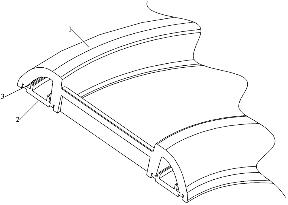
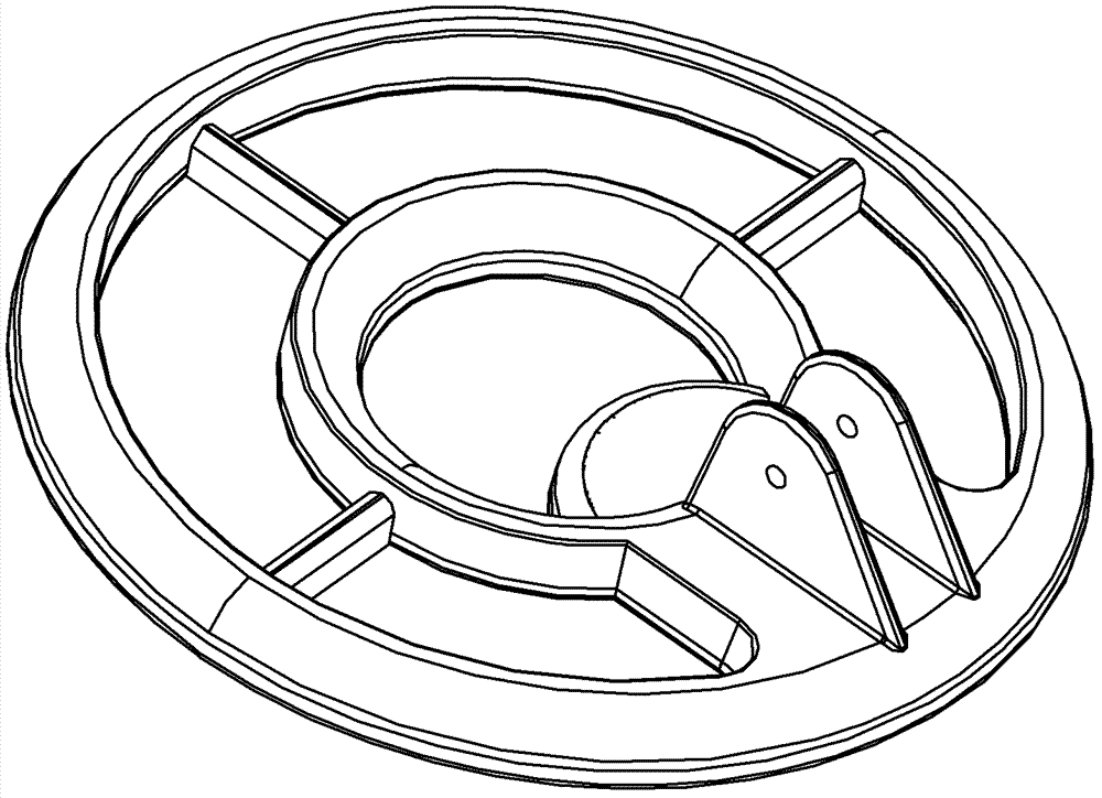
[0010] Such as figure 1 and figure 2 As shown, the detection disk in the metal detector of the present invention includes a disk cover 1, a disk bottom 2 and a hot-melt strip 3, and the disk cover 1 is fixed to the bottom 2 of the disk by the hot-melt strip 3, and the disk cover is specifically bonded by means of ultrasonic thermal fusion. It resonates with the bottom of the pan under the action of ultrasonic waves. The function of the hot-melt strip is to generate heat during the resonance and be in a molten state. After pressurization, the pan cover and the bottom of the pan are integrated. The shape of the hot-melt strip is an isosceles triangle, and the sharp part of the triangle is the place where the ultrasonic wave starts to vibrate.

[0011] The invention uses an ultrasonic hot-melt machine to pro...


PUM


Abstract

The invention discloses a detection disc in a metal detector, which comprises a disc cover, a disc bottom and a hot melting strip, wherein the disc cover is fixed with the disc bottom by the hot melting strip; and the hot melting strip is in a shape of isosceles triangle. The hot melting strip is used by the detection disc in the metal detector, and gluewater is not used, so that the pollution is prevented.

Description

technical field [0001] The invention relates to a metal detector, in particular to a detection disc in the metal detector. Background technique [0002] The metal detector is mainly used to detect and identify precious metal objects buried underground. Its basic principle is to use the transmitting coil to emit continuous waves or pulse waves to establish a stable strain magnetic field in the detection area. When a metal object enters the detection area, the strain When the magnetic induction of the magnetic field changes, the receiving coil receives the changing current of the magnetic induction. After analysis, amplification and classification, adaptation and corresponding processing and output, display and alarm are realized. [0003] The transmitting coil and receiving coil are distributed in the detection coil. The detection coil synthesis technology adopts the joint surface of the cover and the bottom of the disc to inject glue to be cured. The existing detection coil ...

Claims


Application Information

Patent Timeline
Patent Type & Authority Applications(China)
IPC IPC(8): G01V3/10
Inventor 施旭东
Owner SHANGHAI 21ST CENTURY ELECTRONICS EQUIP
Why Eureka
Try Eureka