Supercharge Your Innovation With Domain-Expert AI Agents!

Rapier and Projectile Looms

A shuttle loom, rapier technology, applied in the field of gripper looms, can solve the damage of wear-resistant elements, gripper belt warps and/or guide hooks, can not ensure that the wear-resistant elements and rapier are aligned and firm, careless Fastening and other issues, to prevent unintentional relative movement, fast and simple assembly

Active Publication Date: 2014-10-29
PICANOL NV
View PDF10 Cites 0 Cited by
  • Summary
  • Abstract
  • Description
  • Claims
  • Application Information

AI Technical Summary

Problems solved by technology

[0008] The combination of wear elements and gripper straps known from the prior art has the disadvantage that alignment and firmness of the wear elements with the rest of the rapier and more specifically with the gripper straps cannot be ensured
Every known solution always has the risk that during assembly, for example due to careless fastening, dust, defective screws or due to minor deformations, the wear-resistant element will not be properly aligned with respect to the gripper strip
This is especially disadvantageous when the wear element of the rapier can achieve contact with the warp thread or the guide hook, wherein incorrectly aligned wear element, gripper tape, warp thread and / or guide hook can all be damaged

Method used


Image

  • Rapier and Projectile Looms
  • Rapier and Projectile Looms
  • Rapier and Projectile Looms

Examples


Embodiment Construction

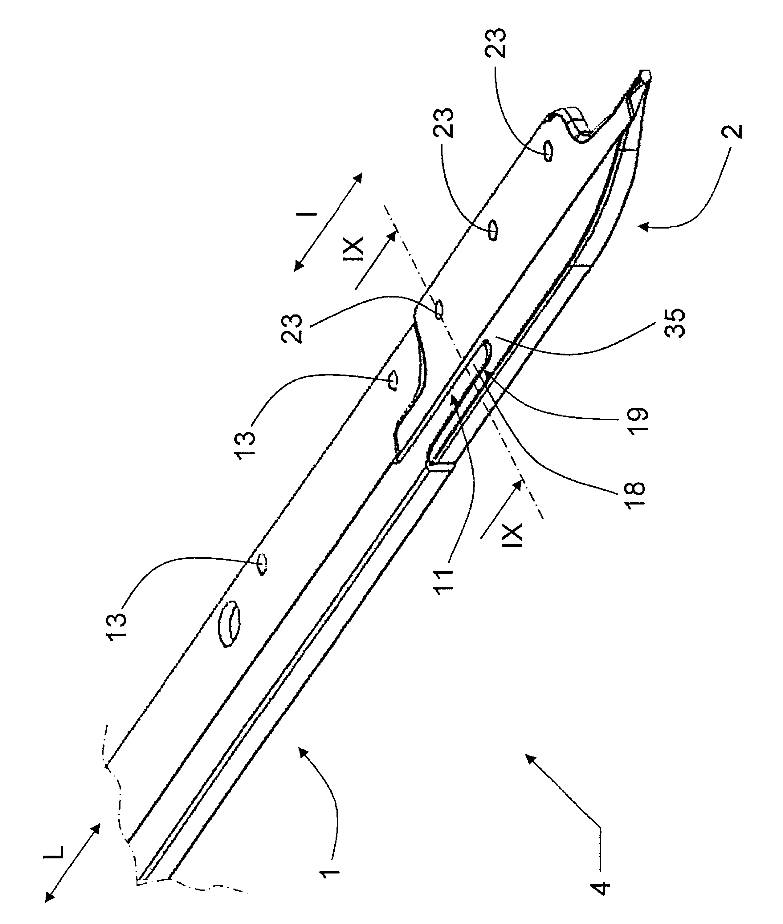
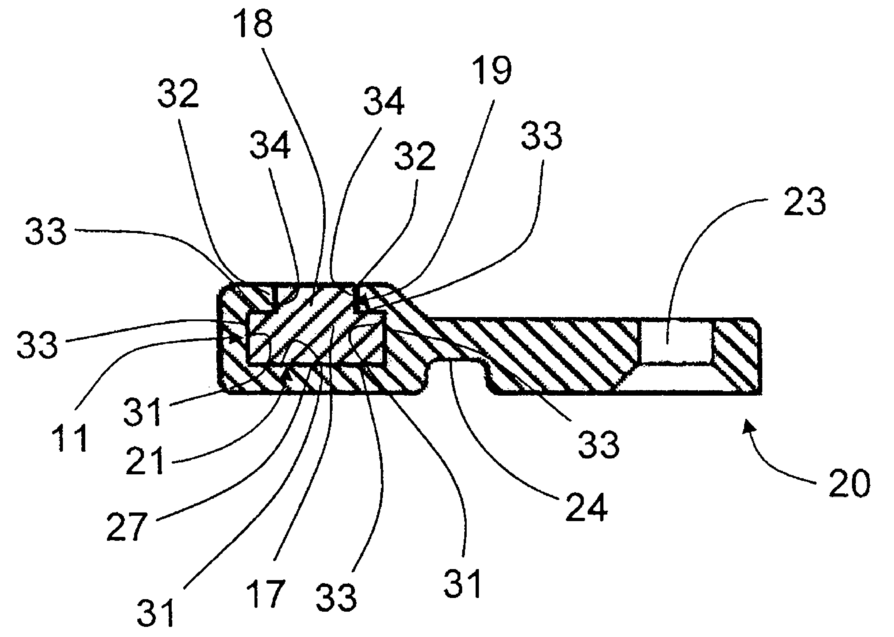
[0043] Figure 1 to Figure 5 A first embodiment of a rapier 1 is shown comprising a gripper band 2 provided with a stiff top 10 and a wear element 20 which may be removably connected to the stiff top 10 . figure 1 A view is shown of the rigid top 10 and the wear-resistant element 20 before they are connected. The rigid top 10 comprises an elongated tongue 11 extending beyond the rigid top 10 , while the wear-resistant element 20 comprises a recess 21 which can cooperate with the tongue 11 . figure 2 A view showing the connection of the rigid top 10 and the wear-resistant element 20 . image 3 A view is shown of a rapier 1 with a gripper 3 attached to the rapier 1 on a rigid top 10 and a wear-resistant element 20 . In this case, the gripper 3 is attached near the front end 4 of the rapier 1, where the wear element 20 is also fitted. Figure 4 A section is shown at the tongue 11 and the recess 21 of the rigid top 10 and shows how the wear-resistant element 20 is guided by th...


PUM


Abstract

Rapier for a gripper weaving machine and gripper weaving machine, wherein the rapier (1) comprises a gripper band (2) and a wear-resistant element (20) which is added to the gripper band (2), the gripper band (2) comprises a stiff top (10) to which the wear-resistant element (20) can be connected, the stiff top (10) and the wear-resistant element (20) comprise complementary connecting parts (6, 7) which comprise a tongue (11) and a recess (21), the tongue (11) can be introduced by sliding it into the recess (21) in an introduction direction (I) and the tongue (11) is held in the recess (21) in a form-fitted manner in the directions other than the introduction direction (I), wherein a gripper (3) can be attached to the stiff top (10) and to the wear-resistant element (20) by fastening elements (14, 24) which are positioned in zones (15, 16) which do not coincide with a connecting part (6) of the wear-resistant element (20) or with a connecting part (7) of the stiff top (10).

Description

technical field [0001] The invention relates to a rapier for a gripper loom, wherein said rapier comprises a gripper belt and a wear-resistant element arranged at the front end of said rapier. Furthermore, the invention relates to a wear element for such a rapier and to a projectile loom with such a rapier. Background technique [0002] With regard to projectile looms, also known as rapier looms, a projectile is attached to the front end of the rapier for moving the projectile through the shed. Rapiers for projectile looms generally comprise either a flexible gripper band or a relatively rigid gripper band, also called a gripper bar. Gripper belts are generally generally made of a reinforced and relatively flexible material, such as epoxy resin with carbon fibers. The front end of the rapier is usually intended to guide the rapier and is usually reinforced and of a stiff design to ensure good guidance of the rapier through the shed. Also, the front end of the rapier is us...

Claims


Application Information

Patent Timeline
Patent Type & Authority Patents(China)
IPC IPC(8): D03D47/20D03D47/23
CPCD03D47/20D03D47/23
Inventor D.莫内克利
Owner PICANOL NV
Features
  • R&D
  • Intellectual Property
  • Life Sciences
  • Materials
  • Tech Scout
  • Unparalleled Data Quality
  • Higher Quality Content
  • 60% Fewer Hallucinations
Learn More