
Antenna structure design capable of measuring deformation

An antenna structure and deformation technology, applied in the microwave field, can solve the problems such as the inability to integrate sensors and arrays, and the inability to realize real-time measurement, achieve communication stability and high anti-interference ability, avoid shielding problems, and strong environmental adaptability Effect

Inactive Publication Date: 2021-02-05
CHINA ELECTRONICS TECH GRP CORP NO 14 RES INST
View PDF10 Cites 2 Cited by
  • Summary
  • Abstract
  • Description
  • Claims
  • Application Information

AI Technical Summary

Problems solved by technology

However, traditional optical measurement cannot highly integrate the sensor with the front, nor can it achieve real-time measurement

Method used


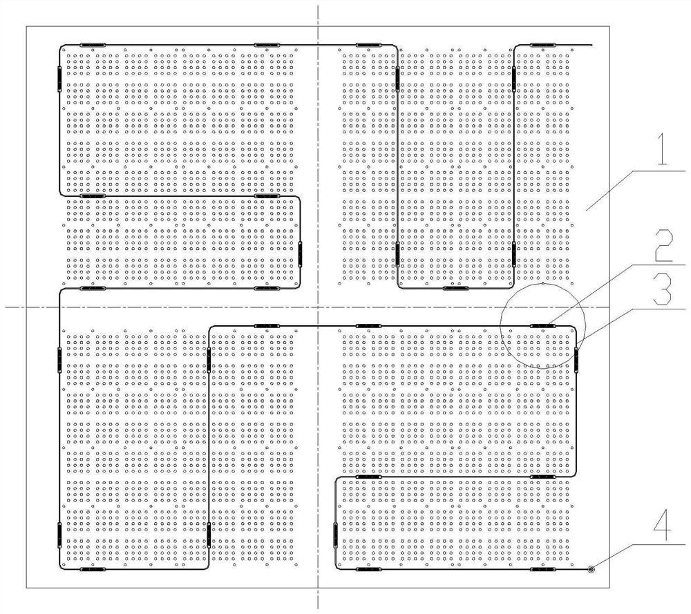
Image

  • Antenna structure design capable of measuring deformation
  • Antenna structure design capable of measuring deformation
  • Antenna structure design capable of measuring deformation

Examples


Embodiment Construction

[0014] The technical solution of the present invention will be specifically described below in conjunction with the accompanying drawings.

[0015] Such as Figure 4 As shown, the communication optical fiber 3 is embedded in the optical fiber cable groove 13 reserved in the reflective panel 1, and is glued to the cable groove by dispensing epoxy glue 6, flush with the end face, and does not affect the equipment installation on the surface of the reflective plate.

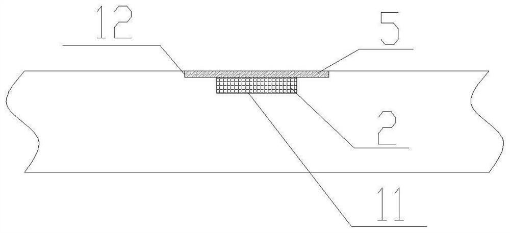
[0016] Such as image 3 As shown, the optical fiber sensor 2 is embedded in the sensor installation groove 11 with a depth of 1.2 mm reserved in the reflective panel 1, and is welded to the installation groove by laser spot welding. The end faces are flush and do not affect the installation of equipment on the surface of the reflector.

[0017] Such as figure 2 As shown, the optical fiber sensor 2 is connected in series by the communication optical fiber 3, and several sensors are arranged vertically and horizon...


PUM


Abstract

The invention discloses an antenna structure design capable of measuring deformation. A sensor network is arranged on the front surface of a reflecting panel, a reserved mounting groove is embedded, equipment mounting on the surface of the reflecting panel is not influenced, strain data is generated along with the deformation of the reflecting panel, the real-time morphology of the reflecting surface of an antenna is calculated by adopting a reconstruction algorithm, and an ultrathin optical fiber sensor is adopted, only 1.2 mm grooves need to be formed in the panel, rigidity losses and a structural interference stress caused by array surface lightening and thinning are avoided, problems that naked grating gluing reliability is poor and a screw joint size of an integrated sensor is large are solved, parallel connection different from resistance strain gauges in series connection is adopted, cables are reduced by more than 90%, stability and an anti-interference capacity are high, and the electromagnetic interference problem is avoided.

Description

technical field [0001] The invention belongs to the field of microwave technology, and in particular relates to an antenna structure reconfiguration technology. Background technique [0002] As the core of the radar, the phased array antenna directly determines the strength of the radar detection capability. With the continuous improvement of antenna technology and the improvement of operational requirements, phased array antennas are gradually developing in the direction of large-caliber and thinner, which brings huge problems to the service guarantee of phased array radars. [0003] The phased array antenna contains hundreds or thousands of antenna elements. By changing the phase of each antenna element, beam scanning is realized, and the electrical performance is highly coupled with the position accuracy of the array element and the accuracy of the reflector. Thinning and thinning will lead to insufficient stiffness of the antenna, and under the influence of environmenta...

Claims


Application Information

Patent Timeline
Patent Type & Authority Applications(China)
IPC IPC(8): G01B11/16G01S7/02
CPCG01B11/18G01S7/02
Inventor 唐宝富戴苏亚顾叶青程春红王涛
Owner CHINA ELECTRONICS TECH GRP CORP NO 14 RES INST
Learn More