Wheel deburring device

A technology for deburring and wheel removal, which is applied in grinding machines, metal processing equipment, grinding/polishing equipment, etc. It can solve the problems of dust that is harmful to the human body, low brush line speed, and low efficiency, and achieves safe and stable performance and a high degree of automation. , the effect of simple structure

Active Publication Date: 2013-02-06
CITIC DICASTAL
View PDF8 Cites 14 Cited by
  • Summary
  • Abstract
  • Description
  • Claims
  • Application Information

AI Technical Summary

Problems solved by technology

The traditional deburring method is to use a large disc brush to directly brush the back cavity. For wheel types with complex spoke shapes and small and many windows, although the linear speed of the outermost edge of the brush is high, the In fact, the bristles cannot touch the corners of the junction between the rim and the spokes, and the removal effect is very unsatisfactory; and the bristles on the brush corresponding to the corners of the root of the flange have a very low linear speed, which also makes the removal effect here unsatisfactory. These positions often need manual grinding; not only the efficiency is low, but also the dust generated by grinding is very harmful to the human body

Method used


Image

  • Wheel deburring device
  • Wheel deburring device
  • Wheel deburring device

Examples


Embodiment Construction

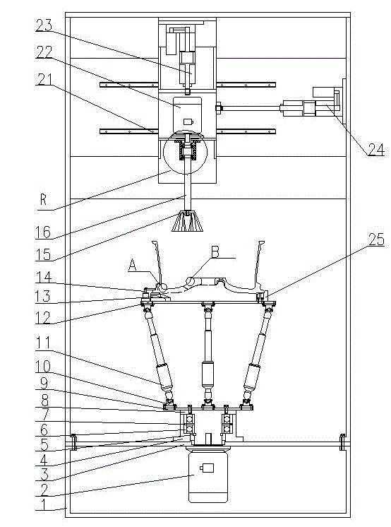
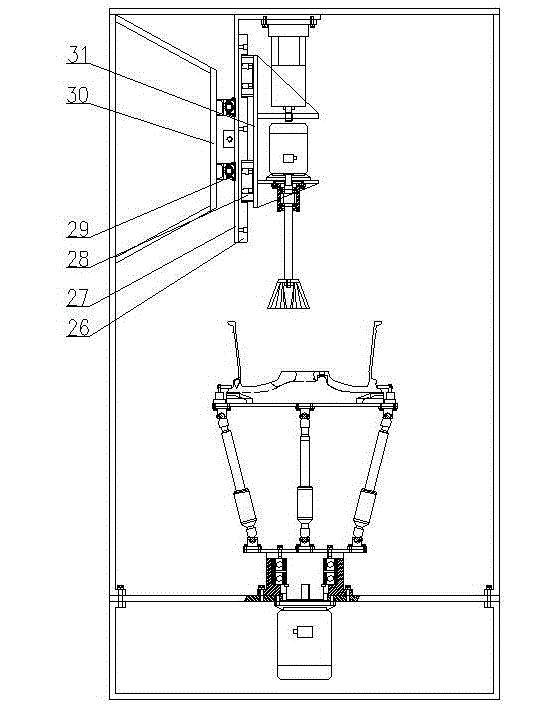
[0014] The details and working conditions of the specific device proposed according to the present invention will be described below in conjunction with the accompanying drawings.

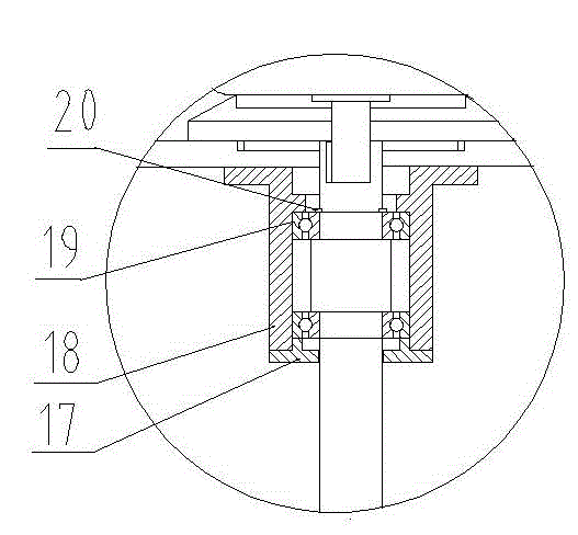
[0015] The device consists of frame 1, motor 2. Partition 3. Bearing seat 4. Circlip for shaft 5. Bearing 6. Spacer sleeve 7, rotating shaft 8, fixed platform 9, universal hinge 10, servo electric cylinder 11, moving platform 12, end face positioning block 13, corner cylinder 14, bowl brush 15, drive shaft 16, gland 17, bearing seat 18. Bearing 19. Circlip for shaft 20. Parallel guide rail 21. Motor 22. Lifting servo electric cylinder 23, translational servo electric cylinder 24, radial positioning block 25, vertical guide rail 26, connecting plate 27, vertical guide rail slider 28, parallel guide rail slider 29, guide rail base 30 and sliding base 31 ,

[0016] The frame 1 is divided into upper and lower parts, and the upper end is fixed with a bearing seat 4 and the lower end is...


PUM


Abstract

The invention discloses a wheel deburring device, which consists of a rack, a motor, a clapboard, a parallel mechanism, a rotating structure of the parallel mechanism, a clamp system, a bowl-shaped brush and a lifting and translation system, wherein the rack is divided into an upper part and a lower part which are connected with the clapboard; the parallel mechanism and the rotating structure of the parallel mechanism are fixed to the upper end of the clapboard, and the motor is fixed to the lower end of the clapboard; the clamp system is used for fixing a hub on a moving platform of the parallel mechanism; a lifting and translation electric servo cylinder is used for performing initial adjustment on the position of the rotating bowl-shaped brush through four guide rails in the vertical and translation directions and in a same plane, and then fixing the rotating bowl-shaped brush; and when the motor drives the parallel mechanism, the hub and the clamp to rotate, the pose of the hub is continuously adjusted through the parallel mechanism, and a back cavity of the hub, particularly each corner part of the hub, can be always positioned in an optimal contact posture with the bowl-shaped brush, and therefore, machining burrs on the various parts, particularly the corner parts, of a wheel can be effectively removed.

Description

technical field [0001] The invention relates to a deburring device, in particular to a parallel wheel deburring device. Background technique [0002] In the production process of automobile wheels, it is a very important process to effectively remove the back cavity and corner burrs produced after machining, and the removal effect will directly affect the subsequent surface treatment effect. The traditional deburring method is to use a large disc brush to directly brush the back cavity. For wheel types with complex spoke shapes and small and many windows, although the linear speed of the outermost edge of the brush is high, the In fact, the bristles cannot touch the corners of the junction between the rim and the spokes, and the removal effect is very unsatisfactory; and the bristles on the brush corresponding to the corners of the root of the flange have a very low linear speed, which also makes the removal effect here unsatisfactory. These positions often need manual grin...

Claims


Application Information

Patent Timeline
Patent Type & Authority Applications(China)
IPC IPC(8): B24B9/00
Inventor 薛博文郭建东刘伟东鲁月新于志远
Owner CITIC DICASTAL
Why Eureka
Try Eureka