Insert molded body and radiation structure

A technology of insert molding and bonding holes, applied in the direction of coating, etc., can solve the problem of low adhesion between resin parts and metal parts, and achieve the effect of smooth heat transfer and sufficient adhesion

Inactive Publication Date: 2013-02-06
POLYPLASTICS CO LTD
View PDF1 Cites 5 Cited by
  • Summary
  • Abstract
  • Description
  • Claims
  • Application Information

AI Technical Summary

Problems solved by technology

[0007] However, insert molded products have a problem in that the adhesive force between resin parts and metal parts is weaker than composite products manufactured using adhesives, etc.

Method used


Image

  • Insert molded body and radiation structure
  • Insert molded body and radiation structure
  • Insert molded body and radiation structure

Examples


no. 1 approach

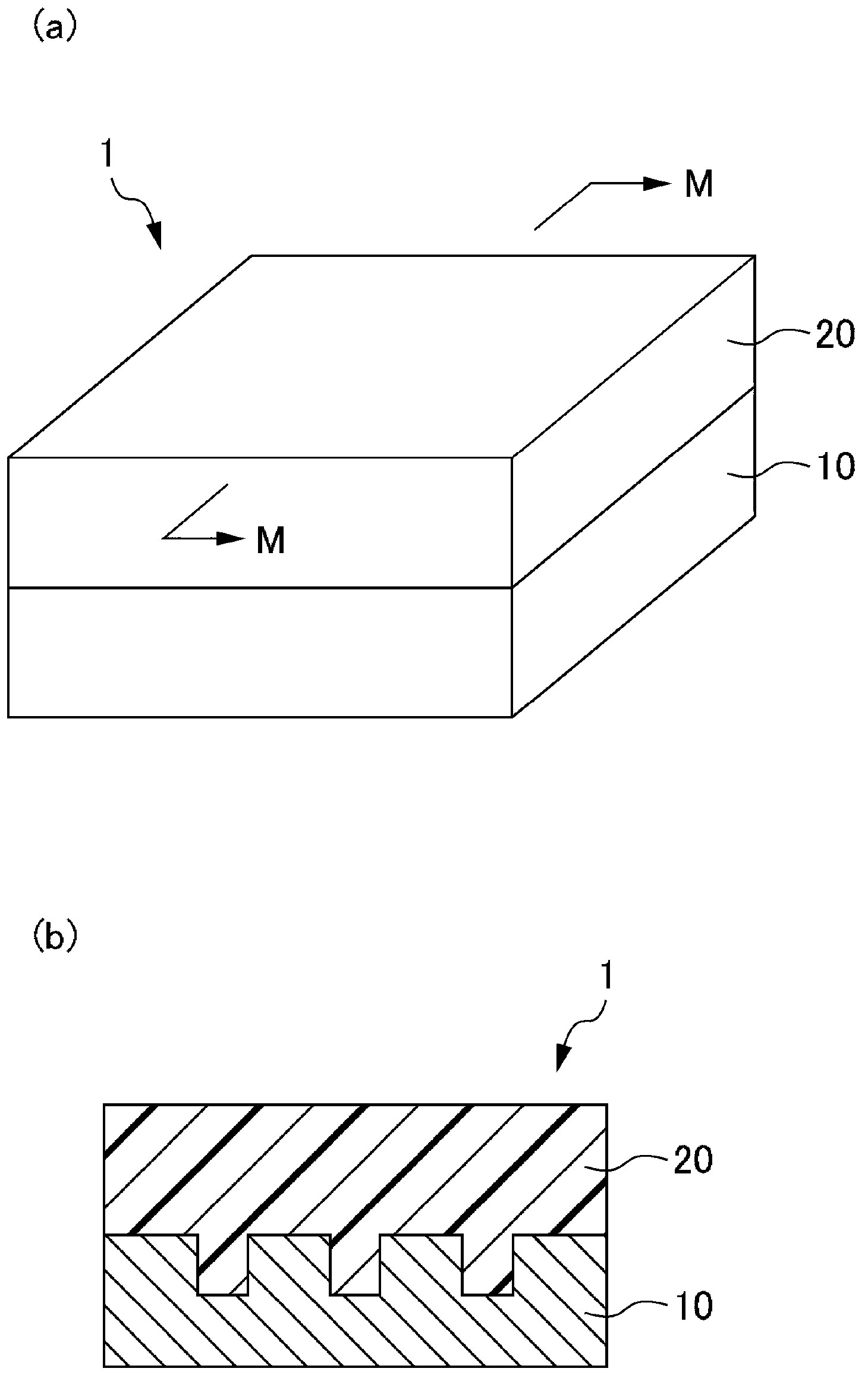
[0055] figure 1 It is a schematic diagram which shows the insert molding of 1st Embodiment, (a) is a perspective view, (b) is MM cross-sectional view.

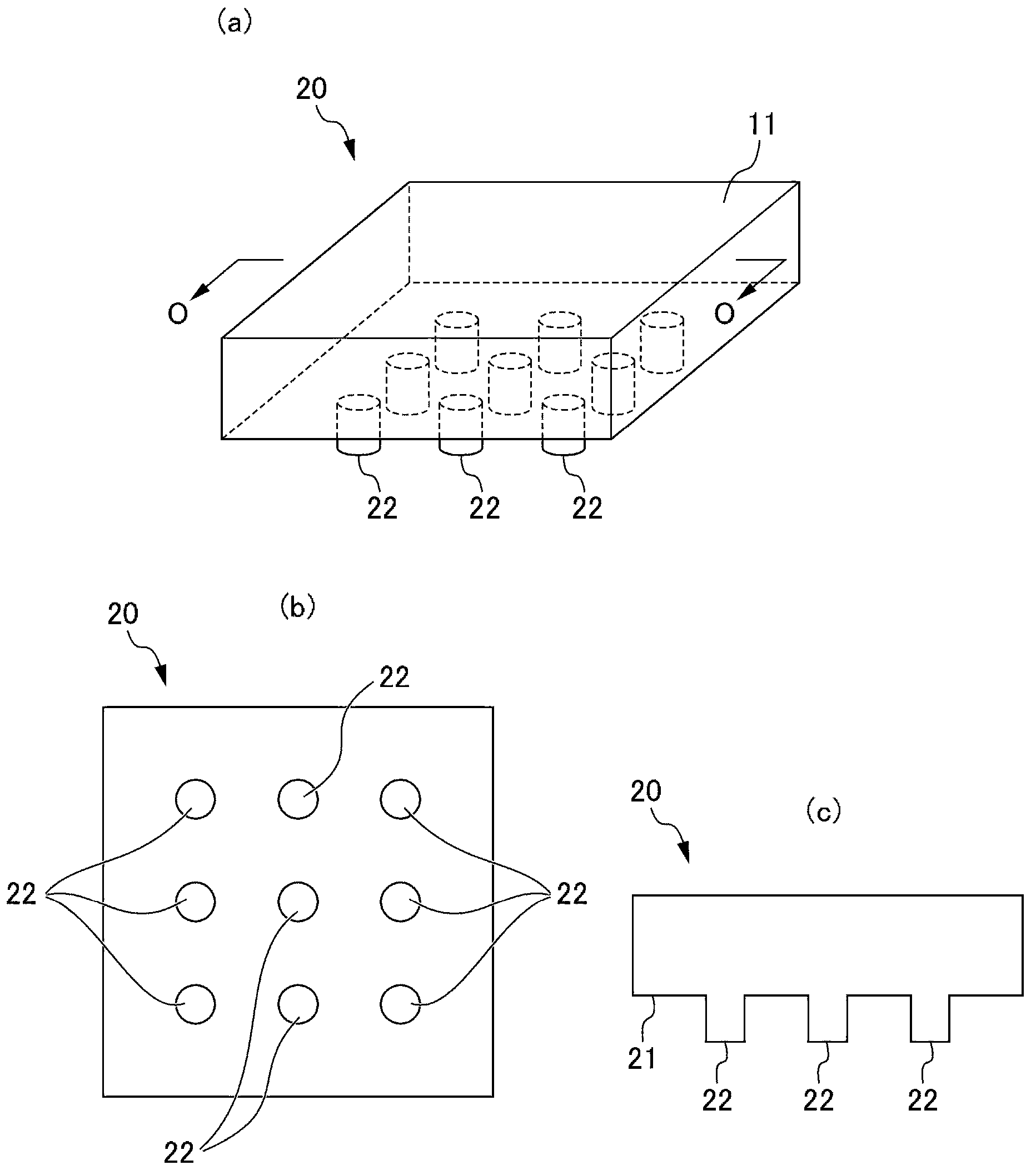
[0056] like figure 1 As shown, the insert molded body 1 of this embodiment includes a metal member 10 and a resin member 20 . like figure 1 As shown, it is formed by laminating the resin component 20 on the metal component 10 . Additionally, if figure 1 As shown in (b), the resin member 20 enters into a hole (joint hole described later) formed in the metal member 10 .

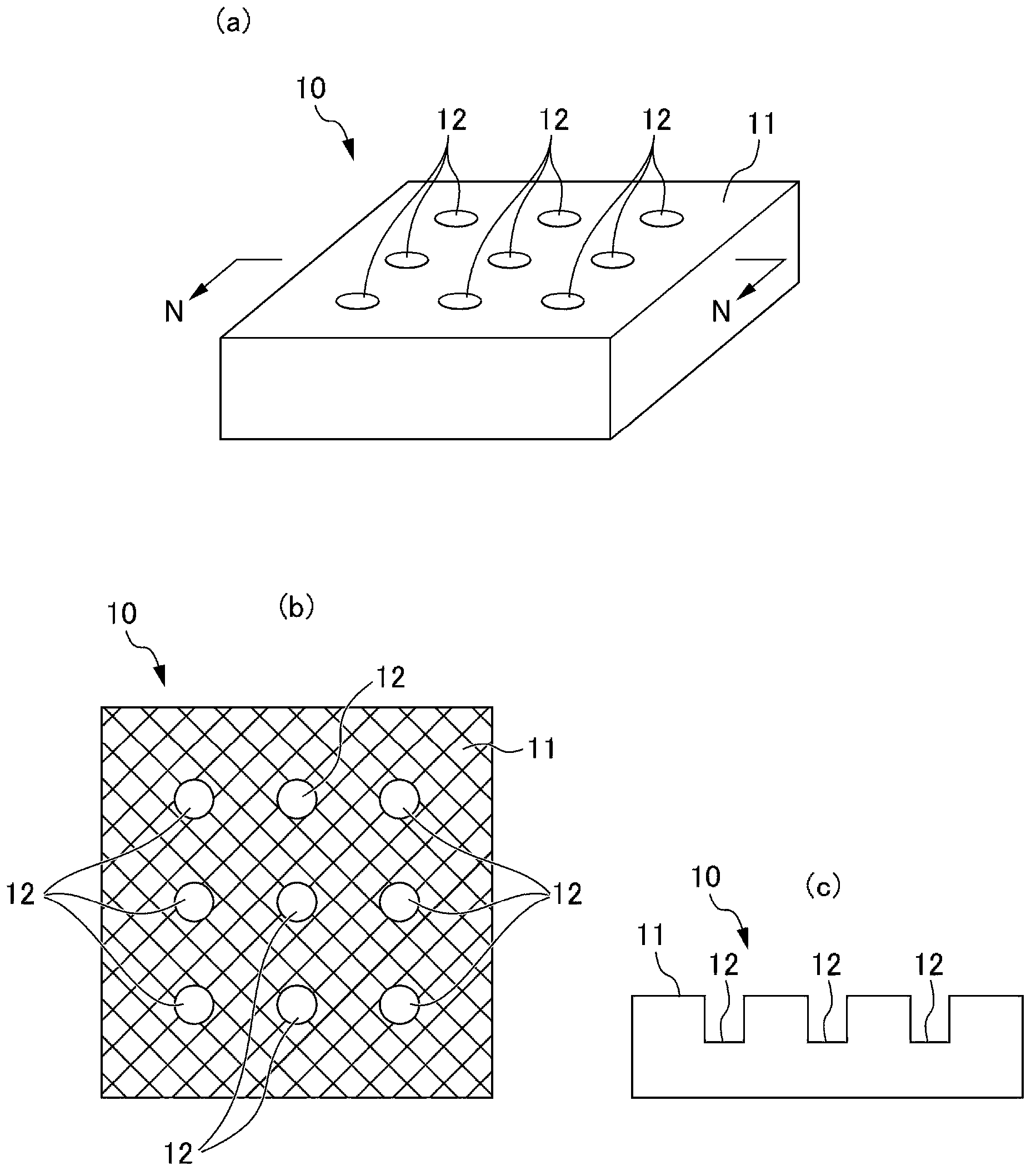
[0057] figure 2 It is a schematic diagram which shows the metal member 10, (a) is a perspective view, (b) is a top view, (c) is NN cross-sectional view.

[0058] like figure 2 As shown, the metal component 10 is a plate-shaped component. In addition, the metal part 10 has a joint surface 11 and two or more joint holes 12. The joint surface 11 is one surface constituting the metal part 10, which is in contact with a resin part 20 described later; ...

no. 2 approach

[0100] Next, edge reference Figure 4 A second embodiment of the insert molded article of the present invention will be described. The insert molded body 1A of the present embodiment is rectangular hexahedron like the insert molded body 1 of the first embodiment, Figure 4 It is a schematic diagram which shows the cross section of the insert molding 1A of 2nd Embodiment. It should be noted that in the description of the second embodiment and thereafter, the same reference numerals are assigned to the same constituent elements, and the description thereof will also be omitted.

[0101] The insert molded body 1A of the second embodiment is mainly different from the first embodiment in that the joint hole 12A formed on the joint surface 11A of the metal member 10A is a through hole penetrating the joint surface 11A and its rear surface.

[0102] In addition, since the bonding hole 12A penetrates the bonding surface 11A and its back side surface, the area S of the bonding surfac...

no. 3 approach

[0107] Next, edge reference Figure 5 A third embodiment of the insert molded article of the present invention will be described. The insert molded body 1B of the present embodiment is in the same rectangular hexahedron shape as the insert molded body 1 of the first embodiment and the insert molded body 1A of the second embodiment, Figure 5 It is a schematic diagram which shows the cross section of the insert molding 1B of 3rd Embodiment.

[0108] The insert molded body 1B of the third embodiment is different from the first embodiment in that the joint hole 12B formed on the joint surface 11B of the metal member 10B penetrates the joint surface 11B and the surface on the back side; at least a part of the joint hole 12B In the joint hole 12B, the cross-sectional area in the depth direction at a predetermined depth is smaller than the cross-sectional area in the depth direction at a position deeper than the predetermined depth.

[0109] The shape of the engaging hole 12B is a...


PUM

PropertyMeasurementUnit
areaaaaaaaaaaa
diameteraaaaaaaaaa
diameteraaaaaaaaaa

Abstract

The present invention provides an insert molded body and a radiation structure. The insert molded body can be manufactured by a method with high production efficiency. The adhesion force between a resin member and a metal member is sufficient, and the heat transmission between the resin member and the metal member is smooth. The insert molded body has the resin member and the metal member. The metal member includes two or more engaging holes. The engaging holes are formed on the mating surface of the resin member in a dispersed form. The resin member has a convex portion which is inserted into the engaging holes. At least one engaging hole has the opening area more than?? 0.44 mm<2> and less than 19.63 mm<2>. The area surrounded by the outer peripheral of ??the bonding surface of the resin member and the metal member is S1, the sum of the opening area of the engaging hole on the engagement surface is S2, and the proportion of S2/S1 meet a specific inequality (I).

Description

technical field [0001] The present invention relates to an insert molded body and a heat dissipation structure. Background technique [0002] Composite products in which metal parts such as aluminum and aluminum alloys are integrated with resin parts made of thermoplastic resin compositions are currently used in automotive interior parts such as console boxes around instrument panels, interior parts, Exterior parts of electronic equipment such as digital cameras and mobile phones, etc. [0003] As a method of integrating metal parts and resin parts, there is a method of bonding using an adhesive or a double-sided adhesive tape; providing a fixing member such as a folded piece or a hook on a metal part and / or a resin part, and using the fixing method A method of fixing both parts; a method of joining with screws, etc. Among them, the method using an adhesive is a convenient method and is frequently performed. [0004] Here, adhesives for integrating metal parts and the lik...

Claims


Application Information

Patent Timeline
Patent Type & Authority Applications(China)
IPC IPC(8): B29C45/14
CPCB29C45/14B29C2045/14868B29K2081/04B29K2101/12B29K2705/02B29K2995/0013
Inventor 近藤秀水木坊子真治
Owner POLYPLASTICS CO LTD
Why Eureka
Try Eureka